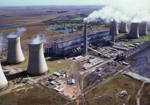
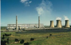
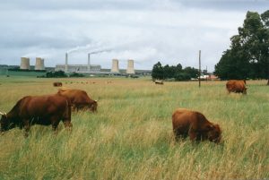
Hendrina Power Station
The first unit went into operation in 1970 and the last in 1976. The station’s power is fed into the 400 kV network.
In the same year, 1965, a contract to supply the coal requirements of the power station was awarded to Trans-Natal Coal Corporation Ltd. This led to the establishment of Optimum as an underground mine. Optimum Colliery is situated on the Witbank coalfield, which is the main coal-producing area of South Africa. Because of the shallowness of the coal seams in some areas, provision was made in the late 1960s to sue opencast mining methods, together with underground operations. The mine is currently producing approximately 12 million tons of raw coal per annum, using draglines. Optimum Colliery will continue to supply Hendrina power station for its full life expectancy of 50 years.
Between 1995 and 1997, five of Hendrina’s ten units were refurbished. They now boast some of the most advanced system control technology in the world. The station’s 5-in-1 control room was the first in the Southern Hemisphere. From 2001 to 2005 the remainder of Hendrina’s ten units was refurbished, however not to the same extent as the previous units’ refurbishments. Hendrina received a gold award from the National Productivity Institute.
Basic Cycle
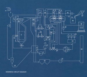
Coal is obtained for the Optimum Colliery and transported by a duplicate overland conveyor system, with a route length of 2 290m, to four coal staiths and an emergency stockpile. In addition, emergency facilities are provided to accept coal delivered by rail. From the staithes the coal is fed into boiler bunkers, of which there are six per boiler, each providing a storage capacity of 24 hour’s operation at full load. From the bunker a variable coal feeder feeds the coal into a vertical spindle mill, of which there are two types: the ball-and-ring type found in Units 1 to 7 and the roller type in Units 8 to 10. Here the coal is ground into a very fine powder.
Forced-draught fans draw warm air from the top of the boiler house and the air is preheated by means of air heaters. The heated air divides into secondary air and a remaining portion, which is boosted by the primary air fan to become primary air. The primary air transports the pulverised coal from the mill to the pulverised-fuel burners. Secondary air is then added to the burners to aid the combustion process in the furnace. On initial lighting up of the boiler, burners supplied with fuel oil are inserted into the boiler and electrically ignited. Once the unit load reaches 80MW, the first mill supplying pulverised coal is placed on load. The second and third mills are then progressively placed on load, and once the furnace protection as armed the oil burners are retracted.
The boilers have a burn rate of about 105 tons per hour; producing coarse ash and fly ash at a ratio of 1:6. The coarse ash falls to the bottom of the boiler, where it is cooled by quenching spray nozzles and collected in water-filled hoppers. Then it is pumped to the ash disposal dams.
The fly ash is carried in the flue gases to the precipitators or fabric filter plant where 99.5% to 99.8% of it is removed and collected I the dust hoppers. The fly ash is ten extracted from the hoppers by hydro vac units, which in effect water ejectors are creating an ash-water mixture. This is discharged into the ash pit via sluice ways. Ash pumps then pump the ash-water mixture to the ash disposal dams. Before the flue gases enter the precipitators, on Units 2 and 4, SO³ is injected into them to decrease the resistivity of the ash, thereby enhancing the efficiency of the electrostatic precipitators or fabric filer plants, to be discharged into the atmosphere via the two 155 m high smokestacks.
Steam circuit
Heat produced by the burning coal is absorbed by the demineralized water contained in the boiler furnace wall tubing. From the boiler drum, which separates the water and steam, additional heat via the various super heaters produces superheated steam at a final steam temperature of 543ºC and 11,0 MPa (gauge). The super- heated steam gives each boiler a maximum continuous rating at the turbine stop valve of 214 kg/s.
The superheated steam leaves the final super heater and is fed into the high-pressure turbine where it expands, releasing part of it energy and rotating the turbine at 300 r/min (5) Hz). After exhausting from the high-pressure turbine, the steam, now at 125ºC and 0.2 MPa, is fed into the low-pressure turbine at a rate of 150 kg/s. Coupled to the shaft of the two in-line turbines is a generator, where the turbine’s energy is converted into electrical energy at a rated 220 MVA. The generator’s output voltage of 16.5 kV is stepped up by the generator transformer to a transmission voltage of 400 kV. This is then distributed to the national grid.
Cooling and recirculation
Exhaust steam from the low-pressure turbine is condensed in a two-pass surface condenser with a vertically divided water box, containing 16 440 tubes each having a diameter of 23 mm, through which cooling water passes. The condensate is collected I the hot well below the condenser and withdrawn y extraction pumps. From here it is pumped back to the oiler through a feed-heating system and de-aerator.
Fuel Handling
Coal is obtained from the opencast Optimum Colliery and delivered directly by a duplicate overland conveyor system to four coal staithes behind the station (east side) or, alternatively, to an emergency stockpile. The crushed coal, smaller than 50 mm, is transported to the plant at a rate of 480 000 tons a month. The four staithes have capacities of 25 000 tons each, while the capacity of the emergency stockpile is about 100 000 tons. Two systems of incline conveyors, north and south, deliver the coal reclaimed from their respective staithes to the boiler bunkers, of which there are six per boiler. Each bunker has a capacity of 478 tons, giving sufficient storage capacity at the boilers for 24 hours operation at full load.
Mill Feeders
From the boiler bunkers the coal is fed to the corresponding mills via coal feeders. On Units 1 to 5 the Mitchell feeders regulate the coal flow by means of a variable-speed rotary table and a fixed plough. On Units 6 to 10 the newly installed SPIRAC feeders employ a variable-speed shaft-less screw system for coal flow control. The feeders are controlled in direct proportion to the primary airflow. The two induced-draught fans, driven by 6.6 kV motors, draw combustion gases from the furnace over the surfaces of the steam super-heaters, economiser and air preheaters through electrostatic precipitators or fabric filter bags and into the smokestack. The induced-draught fan motors have an output rating of 1 585 kW, 1 129kW and 1 750 kW at 746 r/min for Units 1 and 6 to 10. Units 2 and 4, and Units 3 and 5, giving a design capacity for the fans of about 222 kg/s each. The precipitators or fabric filter bags collect between 99.5% and 99.8% of the dust or fly ash from the flue gases.
Turbines
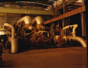
There are 10 Kraftwerk Union (KWU/AEG) impulse-type high pressure and reaction-type low-pressure, double-casing condensing turbines, with and economical continuous rating of 200 MW. Each turbine consists of a high-pressure (HP) and a low-pressure (LP) cylinder. The HP cylinder has an inner and outer casing. A double-casing arrangement is employed to allow a more rapid war-up rate and reduce the probability of high differential temperatures bring experienced. The LP section consists of an inner and an outer casing of welded construction.
The LP end walls are of a double-shell construction, which provides high rigidity and low weight. The steam is exhausted into the main condenser below the LP cylinders. Live steam heated to a of 540ºC and a pressure of 10.5 MPa is admitted into the HP section of the turbine through two hydraulically operated emergency stop valves and four governor valves.
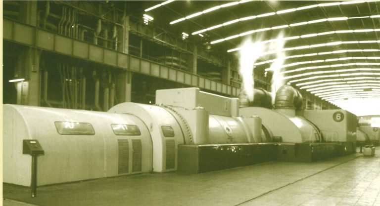
The steam from governor valves 1 and 3 flows from above into the fully admitting nozzle segments arranged in the inner casing while the steam from governor valve 4 flows directly into stage 1 from below without the interposition of nozzles. The steam is expanded into the seven following stages and after redirection into a further none fully admitting impulse stages. Heat energy from the steam is released as the steam passes through the HP turbine and flows into the LP double-flow cylinder at a temperature of 125ºC and a pressure of 0.29 MPa. The steam flows through moving and stationary blades on each side of the LP rotor into the condenser. Steam is exhausted from the LP cylinder at 36.6ºC and 7.0 kPa.
Condensers
The plant is equipped with two-ass regenerative type surface condensers, one per turbine. Air entering the condenser as well as that entrained in the exhaust steam is removed by steam air ejectors as an air vapour mixture and released to the atmosphere, maintaining the vacuum conditions created by the reduction of the volume of the steam as the steam cools down. Condensation takes place over tube bundles composed of 16 440 tubes with a cooling surface area of 11 700m². The condensate is then extracted from the condenser by extraction pumps.
Extraction pumps
Each unit has two centrifugal three-stage condensate extraction pumps. The purpose of the extraction pumps is to extract the condensed steam from the condenser hot-well. The pumps are rated at 100% duty and therefore only one pump is operational under normal operating conditions. The pumps are designed to operate with a suction head ranging from atmospheric pressure to near perfect vacuum conditions. To overcome the resistance of the KP condensate train and the head of pipework to the d-aerator as well as the de-aerator pressure, the pump has a discharge pressure of 1.25 MPa.
Feed-heating plant
The two LP heaters are of the tube-shell type. The condensate passes through a U-shaped tube nest while bled steam from the low-pressure turbine extractions passes through the heater’s shell. The condensate entering LP heater no 1 has an inlet temperature of about 41.8º and its outlet temperature at LP heater o 2 is about 80.8º.
De-aerator
There are two de-aerators per unit, mounted adjacent to the storage tank. The de-aerator supplies a suction head for the boiler feed pumps and removes oxygen and condensable gases from the feed-water. This is achieved by breaking the feed-water into find droplets and subjecting it to bled steam, which boils the water to release entrained gases. De-aeration increases the feed-water temperature 127ºC.
Boiler feed pumps
High pressure feed heaters
Hendrina’s seven cooling towers are of the natural-draught wet-cooling type. The four north cooling towers serviced Units 1 to 5 while the three south towers service Units 6 to 10. At each unit approximately 100 litres of CW evaporates per second at full load. This loss is replaced by raw water supplied from the terminal reservoirs. Each of the cooling tower ponds has a capacity of 8 172 000 litres. The tower has an overall height of 116 m, with a base diameter of 80 m. The temperature drop in the towers is about 11ºC.
Boiler feed-water is demineralised treated water with a conductivity of ˂0.10µS/cm. The demineralisation plant is fed from the water purification plant’s sand filters. The water passes through exchange units, degassing towers, anion exchange units and mixed-bed exchange units, thereby producing demineralised water that is fed into the two demin storage tanks. The amount of potable water and demineralised was produced per day is, on average 2.8 MI and 3 MI respectively, depending on demand.
Sulphur injection plant
The sulphur injection plant was installed to reduce the amount of fly ash emitted into the atmosphere. The purpose of the sulphur injection plant is to decrease the resistivity of the ash, thereby enhancing the efficiency of the electrostatic precipitators, as the precipitators were originally designed to handle fly ash from coal with sulphur content greater than 1.2%. The sulphur plant on the south side has been decommissioned due to the retrofitting of the electrostatic precipitators with fabric filter plants, and at present the sulphur plant on the north side only serves boilers 2 and 4. The fabric filter plants were installed to comply with the increasingly stringent permissible dust emission rates imposed at the Chief Air Pollution Control Officer.
Technical Data
Generating capacity |
1 985 MW |
Fuel |
|
| Mining company | Ingwe |
| Calorific value | ±24.0 MJ/kg (dry basis) |
| Ash Content | ±25.5% (dry basis) |
| Sulphur content | ±0.9% (dry basis) |
| Coal consumed at full load | ± 1 000 tons per hour |
| Total annual consumption | ±6 500 000 tons |
| Coal staithe capacity | 100 000 tons (four staithes with 25 00 tons capacity each) |
| Stockpile capacity | 100 000 tons |
| Boiler bunker capacity | 2 868 tons per unit (six bunkers per unit with 478 tons capacity each) |
| Fuel oil type | FO6 |
| Consumption per boiler | |
| Boilers 1-5 Cold Start Boilers 6-10 Cold Start | 21 tonnes Hot start 5 tonnes 47.4 tonnes Hot start 18 tonne |
Mills |
|
| Manufacturer | |
| Type | |
| Units 1-7 | Babcock & Wilcox 8.SE |
| Units 8-10 | PHI MPS 140 |
| Number | 6 per unit |
| Rotational speed | |
| Babcock & Wilcox 8.SE | 40.0 r/min |
| MPS 140: | 40.7 r/min |
| Rated output | |
| Babcock & Wilcox 8.SE | 24 tons per hour |
| MPS 140: | 21.3 tons per hour |
| Mill motors: | |
| Manufacturer | FEC |
| Output | 216 kW |
| Speed | 980 r/min |
Mill Feeders: Units 1-5 |
|
| Make and type | Mitchell MEB No 60 |
| Number | 6 per unit |
| Minimum coal throughput | 10 tons per hour |
| Maximum coal throughput | 30 tons per hour |
| Throughput control | Variable-speed rotary table with fixed plough |
| Mill Feeders: Units 6-10 | |
| Make and type | Spirotech 420 – Variable shaftless screw |
| Number | 6 per unit |
| Minimum coal throughput | 10 tons per hour |
| Maximum coal throughput | 30 tons per hour |
| Induced-draught Fan Motors | |
| Manufacturer | |
| Units 1,3 and 5-10 | Alsthom |
| Units 2 and 4 | AEI |
| Motor output | |
| Units 1 and 6-10 | 1 585 kW at 746 r/min |
| Units 2 and 4 | 1 129 kW at 744 r/min |
| Units 3 and 5 | 1 750 kW at 746 r/min |
Smokestack |
|
| Number | 2 |
| Height | 155 m |
| Diameter (base) | 20.8 m |
| Diameter (top) | 11.7 m |
| Foundation | 69 piles at a depth of 19.1 m |
Turbines |
|
| Manufacturer | Kraftwerk Union (KWU/AEG) |
| Type | Multi cylinder impulse reaction |
| Rating (generator output) | 222.2 MVA at unity power factor |
| Speed | 3 000 r/min |
| Steam flow to HP cylinder (at 200 MW) | 202 kg/s |
| Steam flow to LP cylinder | 154 kg/s |
| Steam flow at no load | 5.6 k/s |
| Working pressure before ESV’s | 10.5 MPa |
| Working temperature before ESV’s | 538ºC |
| Pressure on LP cylinder | 290.3 kPa |
| Temperature to LP cylinder | 132.5º |
| Heat used per kg of steam | 2 506.3 kj/kWh |
| Heat consumption | 8 884.6 kj/kWh |
| Cycle efficiency | 32% |
Condenser |
|
| Type | Two-pass re-generative type surface condenser |
| Cooling principle | Conduction |
| Number of tubes | 16 440 |
| Tube material | 50 MS 71 Fj8 and stainless steel in the flash box area |
| Total tube surface area | 11 700 m² |
| Condenser pressure (design) | 7.12 kPa |
| Condenser steam pressure | 36ºC |
| Condenser steam flow (design) | 142.2 kg/s |
Extraction pumps |
|
| Motor manufacturer | AEG |
| Supply | 6.6 kV/3-phase/50 Hz |
| Power | 400 kW |
| Pump manufacturer | AEG |
| Type | Centrifugal, 3 stage 100% duty |
| Number per condenser | 2 |
| Delivery flow | 664 m³/h |
| Delivery head | 125m WG |
Condensate at 25ºC | |||
PH | 9.1 to 9.3 | ||
Dissolved O₂ | ˂0.0020 ppm | ||
SiO₂ | ˂0.010 ppm | ||
Fe | ˂0.010 ppm | ||
Oil | nil | ||
K(HI) | ˂0.20µS/cm | ||
Low pressure Feed Heaters | |||
Bled steam temperature to LP heater | |||
No 1 | 63.2ºC | ||
No 2 | 83.8ºC | ||
Condensate inlet temperature | |||
No 1 | 41.8ºC | ||
Condensate outlet temperature | |||
No 1 | 60.2ºC | ||
No 2 | 81.0ºC | ||
De-aerator | |||
Bled-steam temperature | 130ºC | ||
Bled-steam pressure | 300 kPa | ||
Condensate outlet temperature | 127ºC | ||
Feed water after de-aerator dissolved O₂ | 0.01 m³/l | ||
Boiler Feed Pumps (electric) | |||
Manufacturer | KSB Pumps | ||
Number | 2 per unit 50% duty pumps | ||
Type | Multistage (6) centrifugal | ||
Discharge capacity | 101.0 kg/s | ||
Discharge pressure | ±14.5 MPa | ||
Suction pressure | 400 kPa | ||
Pump speed | 2 985 r/min | ||
Flow-rate control | Regulating valve/leak-off valve | ||
Feed pump motor | |||
Manufacturer: | |||
Unit 1 | Mitsubishi | ||
Units 2-10 | ASI and GEC | ||
Motor power output | 2 355 kW | ||
Units 1-10 | |||
Motor speed | 2 985 r/min | ||
Boiler feed pumps (turbine driven) | |||
Pump manufacturer | Sulzer | ||
Number | 1 per unit | ||
Type | Multistage | ||
Discharge capacity (maximum) | 227.0 kg/s | ||
Discharge pressure | ±14.0 MPa | ||
Suction head required | 61.3 m | ||
Turbine manufacturer | AEG Kanis | ||
Steam pressure before ESV | ±2.24 MPa | ||
Steam temperature before ESV | 340ºC | ||
Exhaust pressure | ±250 kPa | ||
Turbine speed | 4 750 –5 200 r/min | ||
Main pump speed | Turbine speed | ||
Flow rate control | Turbine speed / feed water control valves | ||
High-pressure feed heaters | |||
Number | 6 sets of 3 running parallel | ||
Bled steam | |||
No 1A – 1B | 213ºC | ||
No 2A – 2B | 276ºC | ||
No 3A – 3B | 336ºC | ||
Bled Steam pressure | |||
No 1A -1B | 760 Pa | ||
No 2A -2B | 1.4 MPa | ||
No 3A -3B | 2.4 MPa | ||
Water inlet temperature | |||
No 1A -1B | 168.6ºC | ||
No 2A -2B | 194ºC | ||
No 3A-3B | 221ºC | ||
Primary-air fans | |||
Manufacturer | Howden SA Fan Co | ||
Number | 6 per unit | ||
Type | Single inlet, centrifugal | ||
Flow control | |||
Units 1-4 | Fluid drive | ||
Units 6-10 | Horizontal multi-blade damper | ||
Motor | 6.6 kV induction | ||
Motor rated output | |||
Units 1-5 | 272 kW | ||
Units 6 and 7 | 350 kW | ||
Units 8-10 | 153 kW | ||
Motor speed | |||
Units 1 and 8-10 | 1 485 r/min | ||
Units 2-5 | 1 480 r/min | ||
Units 6 and 7 | 1 475 r/min | ||
Fan delivery temperature | 240ºC | ||
Fan delivery pressure | |||
Units 1-5 | 9.03 kPa | ||
Units 6-10 | 6.55 kPa | ||
Capacity | |||
Units 1-5 | 95 m³/s | ||
Units 6-10 | 76 m³/s | ||
Pulverised fuel burners | |||
Number | 24 per unit | ||
Fuel oil burners | |||
Number | 24 per unit | ||
Delivery capacity EACH | |||
Boiler 1-5 | B &W | ||
Unit 1Stack | |||
Units 2-5 | El-Paso | ||
Unit 1-5 / tower number | 5 | ||
Max continuous rating | 200 kg/s | ||
Final steam pressure | 11.0 MPa | ||
Final steam temperature | 540ºC | ||
Height (roof to hopper) | 49.5 m | ||
Width at burner level | 15.95 m | ||
Depth at burner level | 11.07 m | ||
Furnace volume | 4 004 995 | ||
Unit 6-10 / tower number | 5 | ||
Max continuous rating | 214.2 kg/s | ||
Final steam pressure | 11.0 MPa | ||
Final steam temperature | 543ºC | ||
Height (roof to hopper) | 56 m | ||
Width at burner level | 14.77 m | ||
Depth at burner level | 14.75 m | ||
Furnace volume | 4 100 m³ | ||
Air preheaters –Units 1-5 | |||
Manufacturer | Davidson | ||
Type | Regenerative – 2 per boiler | ||
Total heating surface | 10 346 m³ | ||
Rotational speed | ±1.7 r/min | ||
Motor power | 5.6 kW | ||
Air preheaters – Units 6-10 | |||
Manufacturer | Howden | ||
Type | Regenerative – 2 per boiler | ||
Total heating surface | 10 580 m³ | ||
Rotational speed | ±0.79 r/min | ||
Motor power | 11 kW | ||
Precipitators | |||
Manufacturer | |||
Unit 2 | Lurgi | ||
Unit 4 | Brandt | ||
Type | Electrostatic | ||
Construction | Concrete with concrete hopper | ||
Number per boiler | 2 | ||
Number of fields | 3 | ||
Overall collecting efficiency | 98% | ||
Fabric filter plant – Units 1,3 &5 & 6-10 | |||
Type | Pulse jet fabric filer | ||
Casings | 2 per unit | ||
Cells | 2 per casing | ||
Pulsing | Random pulse by means of rotating manifold | ||
Bag type | Polyacrylonitrile | ||
Bag length | 8 m | ||
Quantity of bags | |||
Unit 1,3 & 5 | 8 120 | ||
Units 6-10 | 7 884 | ||
Temperature control | Attemperation | ||
Pulse air supply | Roots-type blowers | ||
Overall collecting efficiency | 99% | ||
Forced draught fans | |||
Manufacturer | Howden | ||
Type | Double inlet centrifugal | ||
Number | 2 per boiler | ||
Volume flow per boiler | |||
Units 1-5 | 257 m³/s | ||
Units 6-10 | 247.7 m³/s | ||
Mass flow per boiler | |||
Units 1-5 | 244 kg/s | ||
Units 6-10 | 247.6 kg/s | ||
Motor output rotary | |||
Units 1-5 | 637 kW | ||
Units 6-10 | 1 057 kW | ||
Motor speed | 990 r/min | ||
Fan control | Radial van control | ||
Cooling water system | |||
Motor manufacturer | |||
North side | Bruce Peebles | ||
South side | GEC | ||
Type | Vertical 6.6 kV squirrel-cage induction | ||
Pump manufacturer | |||
North side | Allen Gwynnes | ||
South side | Sulzer | ||
Discharge capacity | 6.6 m³/s | ||
Speed | 247.5 r/min | ||
Delivery head | 19.5 m | ||
Cooling towers | |||
Number | 7 | ||
Type | Hyperbolic concrete packed with multi-deck plastic | ||
North side | 3 CR 12x-grit | ||
South side | Natural-draught wet cooling | ||
Height | 116 m | ||
Diameter at base of shell | 80 m | ||
Diameter at throat | 51.3 m | ||
Diameter at top | 57 m | ||
Capacity (each) | 11 m³/s, max 14 m³/s | ||
Temperature drop | ±11ºC | ||
Generator – Units 1-10 | |||
Manufacturer | Kraftwerk Union Siemens | ||
Rated capacity | 222.2 MVA | ||
Terminal voltage | 16.5 kV | ||
Current | 7 780 A | ||
Power factor | 0.9 (lagging) | ||
Speed | 3 000 r/min (50 Hz) | ||
Cooling medium | |||
Stator | Demin water and hydroen | ||
Rotor | Hydrogen at 310 kPa | ||
Generator transformers | |||
Manufacturer | |||
Unit 1 | Industrie Elettriche di Legnano | ||
Unit 2 | Oerlikonn | ||
Units 4,6,8,10 | Alsthom | ||
Units 3,5,7,9 | Brrruce Peebles | ||
Rated Capacity | 220 MVA | ||
Rated voltage | |||
LV | 16.5 kV | ||
HV | 420 kV | ||
Unit transformers | Stepdown from 16.5 kV to 6.6 kV | ||
Rating | 20 MVA | ||
Manufacturer | |||
Units 1 and 6-10 | ASEA | ||
Units 2-5 | ASGEN | ||