Artifacts part 1
The objects in this museum are not housed in one building. They can be viewed at various venues throughout South Africa. Some are on loan to, or owned by, cultural bodies and special interest groups. The intent is to preserve these objects for educational purposes, and to be viewed by the widest possible public.
The IONOSPHERIC RECORDER circa 1948
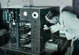
Before submarine cables and satellites for transmitting telephone signals became available in the mid 1970s voice communication with overseas countries depended on short-wave radio. This form of transmission exploited the reflection of radio waves by the Ionosphere located hundreds of kilometres above the surface of the earth. The behaviour of this phenomenon was poorly understood and after WWII an international effort was launched to learn more about the technique.
TECHNICAL INFORMATION
It became essential to understand the variations in height of the Ionosphere and the range of frequencies reflected by these layers. Trevor Wadley, employed by the South African Council for Scientific and Industrial Research’s (CSIR) Telecommunications Research Laboratory, was given the task of developing a suitable instrument for determining these parameters. The height was measured using Radar in the frequency range from 100 kHz to 20 MHz. Wadley devised unique equipment which generated bursts of radio signals over the full frequency range without band switching. Likewise his receiver tuned over the full band in a single smooth sweep. This achievement was unique and proved to be very successful. The results were recorded one frame at time on a 16 mm cinè camera and were shared internationally. Other countries developed similar equipment but the range of frequencies was covered in several steps and could not achieve the same elegant results.
Approximate dimensions 1m x 1m x 1m
The Ionospheric Recorder is part of the South African Institute of Electrical Engineers historical collection.
http://www.saiee.org.za
Tel: +2711 487 3003
Comments or enquiries: [email protected] or [email protected]
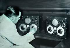
THE WADLEY RECEIVER circa 1952
Following the success of his Ionosphere Recorder, Trevor Wadley realised that the technique could be extended to produce a radio receiver with continuous frequency coverage. In the early 1950s he produced the prototypes shown in the illustration. Following the success of his Ionosphere Recorder, Trevor Wadley realised that the technique could be extended to produce a radio receiver with continuous frequency coverage. In the early 1950s he produced the prototypes shown in the illustration.
TECHNICAL INFORMATION
Based on a stable 1 MHz crystal controlled oscillator the receiver covered all frequencies from 0 to 30 MHz without gaps. There were two frequency-selecting dials, the first chose the desired megahertz range and the second interpolated between successive megahertz steps. By clever design Wadley was able to achieve exceptional frequency stability combined with accurate tuning calibration. It was possible to set the desired frequency on a cold receiver and when the power was switched on the selected frequency would be available to within 5 kHz – such performance had never been achieved previously.
The Royal Navy chose to standardise on this receiver and a small (at that time) British electronics company, Racal, took on the manufacture. It was used all over the world and remained supreme until digital equipment took its place. A transistorised version was manufactured in South Africa, known as the Barlow-Wadley XCR-30, which was very popular with amateur radio enthusiasts all over the world. The Yaesu FRG-7 was produced under licence in Japan.
Approximate dimensions 400mm x 350mm x 250mm
The Wadley Receiver is part of the South African Institute of Electrical Engineers historical collection and can be viewed in Observatory, Johannesburg, South Africa.
http://www.saiee.org.za
Tel: +2711 487 3003
Comments or enquiries: [email protected] or [email protected]
WIRE RECORDER circa 1948
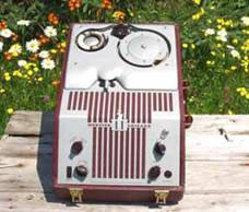
Manufactured by Webster, Chicago.
http://www.videointerchange.com/wire_recorder1.htm
Before the development of oxide based magnetic tape, “glorified” steel piano wire was the dominant media of choice.
The technology of magnetic recording dates back to 1878, when Oberlin Smith proposed the idea of recording telephone signals onto a length of steel piano wire. Over the next thirty years the technology evolved at a “snail’s pace”; stalled by lack of adequate and cost effective electronic amplification. By 1930, advances in electronics allowed the first commercially successful wire recorders to be introduced as dictating machines and telephone recorders in Europe and North America. During WWII, the machines found their way into the BBC who employed banks of them for sending messages to the French underground. Germany broadcast pre-recorded speeches by Adolf Hitler in quick succession from widely separated transmitters to confuse the allies. The early machines used large reels of steel tape at a speed of 1metre/second. The US Army & Navy also employed them for similar purposes in their operations centers. Following the war from 1947 to 1952, wire recorders became popular in America and across Europe, and started showing up in many homes.
The advent of oxide based magnetic tape had many benefits over steel wire…. Mainly the ability to record and playback in stereo. Thus magnetic tape put an end to the wire recording era.
Signals recorded on steel wire recorders have held up quite well over the years and the sound quality was fairly good considering the limited technology of the day.
Approximate dimensions: 430mm long x 290mm wide x 180mm deep.
A Wire Recorder is part of the South African Institute of Electrical Engineers historical collection and can be viewed in Observatory, Johannesburg, South Africa.
http://www.saiee.org.za
Tel: +2711 487 3003
Comments or enquiries: [email protected] or [email protected]
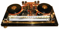
KELVIN CURRENT BALANCE pre-1940
The two coils mounted at the extremities of the pivoted beam were connected in series with four co-axial fixed coils placed above and below the moving coils. The magnetic fields produced by the current interact so as to unbalance the beam and weights are provided to restore the beams to the neutral position. Both AC and DC measurements were possible. International current standards were maintained by similar instruments.
The two coils mounted at the extremities of the pivoted beam were connected in series with four co-axial fixed coils placed above and below the moving coils. The magnetic fields produced by the current interact so as to unbalance the beam and weights are provided to restore the beams to the neutral position. Both AC and DC measurements were possible. International current standards were maintained by similar instruments.
http://www.saiee.org.za
Tel: +2711 487 3003
Comments or enquiries: [email protected] or [email protected]
BURNDEPT ETHOPHONE JUNIOR CRYSTAL SET circa 1925
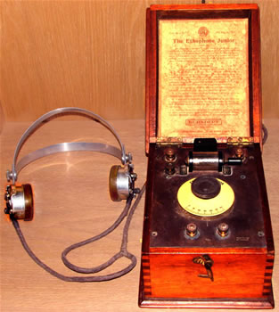
(450kHz – 1200kHz 1925 price about £5)
Most listeners were using crystal sets to receive broadcasts in the early 1920s as they could not afford valve receivers. The Galena crystal and “Cats Whisker” diode detector required frequent readjustment. This, combined with the discomfort of wearing headphones, made listening to broadcasts a dedicated pastime. John Samuel Streeter’s weekly broadcasts of selected gramophone recordings were transmitted from his Cape Town home from 1919 until September 1924.
Approximate dimensions: 150mm x 150mm x 250mm
The Burndept Ethophone Junior Crystal Set is part of the South African Institute of Electrical Engineers historical collection and can be viewed in Observatory, Johannesburg, South Africa.
http://www.saiee.org.za
Tel: +2711 487 3003
Comments or enquiries: [email protected] or [email protected]
MARCONIPHONE circa 1925
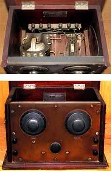
A 2-valve-reaction detector and audio amplifier capable of driving an external loudspeaker at distances up to 60km from the transmitter. It required is a 4V accumulator, a grid bias battery and an HT battery. Long, short and medium waves were selected by means of the plug-in coil which was tuned by the rotating short circuited loop.
The Marconiphone is part of the South African Institute of Electrical Engineers historical collection and can be viewed in Observatory, Johannesburg, South Africa. It was donated to the SAIEE by the late G D Walker.
http://www.saiee.org.za
Tel: +2711 487 3003
Comments or enquiries: [email protected] or [email protected]
JOHANNESBURG OBSERVATORY LIGHTNING RECORDER
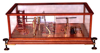
LManufactured in Budapest 1905
This remarkable lightning recorder is the only surviving instrument from the Transvaal Meteorological Station at the Johannesburg Observatory.
Its operation was based on the Marconi coherer wireless telegraphy receiver. The coherer is mounted between the two perforated brass posts to the left of centre of the instrument. Lightning impulses induced in an external antenna caused the coherer to conduct and operate the telegraph relay situated on the right hand side of the instrument.
The relay activated the armature of the central assembly having a striker that de-cohered the coherer. The vertical arm attached to the armature held a pen which wrote on the helical chart rotated by the clock on the extreme left and a gong warned the operators that an event had been recorded.
Dimensions: 630 mm wide x 350 mm deep x 285 mm high
As far as we have been able to determine this is the sole surviving instrument of this type.
For further details see Vermeulen, DJ. 2000. The Historical Interest Group re-discovers Popov. Elektron 17(6), June:13.
The instrument is part of the South African Institute of Electrical Engineers historical collection and can be viewed in Observatory, Johannesburg, South Africa.
http://www.saiee.org.za
Tel: +2711 487 3003
Comments or enquiries: [email protected] or [email protected]
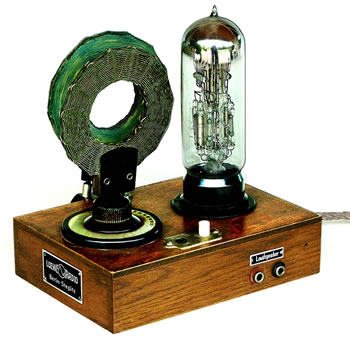
THE FIRST INTEGRATED CIRCUIT
In the 1920s the German manufacture Loewe Radio produced a series of receivers in which several valves and their coupling components were assembled in a common envelope. The only additional items required were the tuning inductance/reaction coils and the tuning capacitor seen in the illustration. This amplifier integration was not easily achieved as each resistor and capacitor had to be individually encapsulated to ensure that they would not contaminate the vacuum.
The main reason for this surprising innovation was to minimise the German licence fee that was based on the number of valves used in a set.
Dimensions: 186 mm wide x 150 mm deep x 190 mm high
The instrument is part of the South African Institute of Electrical Engineers historical collection and can be viewed in Observatory, Johannesburg, South Africa.
http://www.saiee.org.za
Tel: +2711 487 3003
Comments or enquiries: [email protected] or [email protected]
THE BEGINNINGS OF ELECTRONICS
The Contribution of the South African Dr HJ van der Bijl
Electronics started in 1907 when the American entrepreneur, Lee De Forest, invented the first electronic amplifying device. He named it the Audion and it was subsequently known as the triode vacuum tube (valve).
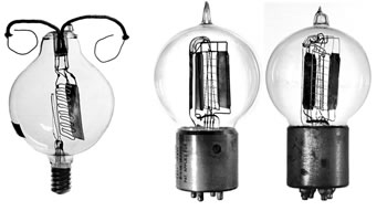
De Forest promoted his invention extensively and made a special version for telephone repeater service (right hand side illustration). He persuaded the Western Electric Company (WE) to pay him $50 000 for the exclusive rights to use the Audion in the telephone industry. His original crude device was not suitable for industrial application and WE assembled a team of scientists to develop it into a practical unit.
In 1914 The South African, Dr Hendrik van der Bijl, analysed its performance mathematically and designed practical tubes for use on the first transcontinental telephone circuit linking New York and San Francisco (centre and right hand illustrations).
Dimensions: 50 mm diameter, 75 mm high & 55 mm diameter, 90 mm high
For more information see Vermeulen, DJ. 1998. The remarkable Dr Hendrik van der Bijl. Proc IEEE 86(12), December: 2445-2454.
All three of these unique valves form part of the South African Institute of Electrical Engineers historical collection and can be viewed in Observatory, Johannesburg, South Africa.
http://www.saiee.org.za
Tel: +2711 487 3003
Comments or enquiries: [email protected] or [email protected]
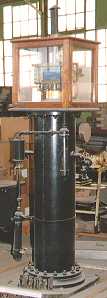
ELECTRICAL POWER FREQUENCY CONTROL
Electrical power suppliers were legally required to maintain mains frequency within close limits. Over 24 hours the total number of cycles generated had to be controlled to ensure that synchronous time keeping devices would remain accurate.
From the mid-1920s until they were linked with Eskom the equipment illustrated was used to monitor the Johannesburg supply frequency. The accurate pendulum clock was kept in step with standard South African time by regular corrections. The mains frequency drove a synchronous clock motor and a comparison between this and the clock time was made every 15 seconds and any discrepancy showed as a deviation between the two pointers of the main dial.
The two smaller clock faces showed mains time and clock time respectively and were useful when the deviation exceeded 3 minutes.
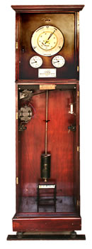
Dimensions: 485 mm wide x 335 mm deep x 1690 mm high
For further information see Vermeulen, DJ. 2001. Mains frequency control. Elektron 18(11), November:29.
The clock is part of the South African Institute of Electrical Engineers historical collection and can be viewed in Observatory, Johannesburg, South Africa.
http://www.saiee.org.za
Tel: +2711 487 3003
Comments or enquiries: [email protected] or [email protected]
THE PROTOTYPE TELLUROMETER
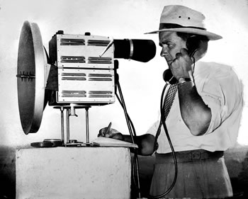
with its inventor Dr TL Wadley (1950)
The Tellurometer measured distances between 3 and 50 km with an accuracy of 3 parts in 106. Instruments were set up at each of the two required points and the distance between them was calculated from the time taken for a radio signal to travel from one end to the other and back again. Once the terminal stations were established the distance could be measured in less than half an hour where previously, using hand methods, it had taken a team several months to complete the same operation.
The Tellurometer was invented and developed by Dr Trevor Wadley working at the CSIR Telecommunications Research Laboratories and was subsequently manufactured in South Africa.
Dimensions: Dish 440 mm diameter, 360 mm front to back, 470 mm high
By 1971 it had earned over R12 million in foreign exchange. This instrument revolutionised land surveying as it became possible to measure distance as quickly and accurately as measuring angles.
The satellite based Global Positioning System has subsequently produced a second revolution in surveying technology.
The Tellurometer is part of the South African Institute of Electrical Engineers historical collection and can be viewed in Observatory, Johannesburg, South Africa.
http://www.saiee.org.za
Tel: +2711 487 3003
Comments or enquiries: [email protected] or [email protected]
EARLY X-RAY TUBE Circa 1900
X-rays were discovered by the German Wilhelm Röntgen in 1895. In 1896 primitive equipment was already in use in South Africa. By the end of the Anglo-Boer war there were probably as many as 20 X-ray units in operation.
This tube is typical of early units that depended on a rather poor vacuum of about 10 mPa to produce cathode rays (electrons). The cathode lies on the right hand side of tube with the anode mounted at an angle in the centre of the tube.
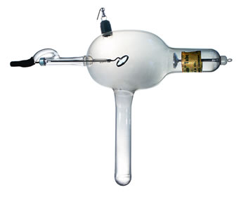
X-rays were discovered by the German Wilhelm Röntgen in 1895. In 1896 primitive equipment was already in use in South Africa. By the end of the Anglo-Boer war there were probably as many as 20 X-ray units in operation.
This tube is typical of early units that depended on a rather poor vacuum of about 10 mPa to produce cathode rays (electrons). The cathode lies on the right hand side of tube with the anode mounted at an angle in the centre of the tube. X-rays were produced when the electrons collided with the anode. Such early tubes produced rather low intensities requiring photographic exposures of several minutes.
Dimensions: 360 mm x 100 mm wide x 320 mm high.
A British supplier, Newton & Co, sold this tube but the manufacturer is unknown.
For further details see Vermeulen, DJ. 2002. Early X-ray equipment: a view from the south. Engineering Science & Education Journ, December 11(6): 231-242. The tube is part of the South African Institute of Electrical Engineers historical collection and can be viewed in Observatory, Johannesburg, South Africa.
http://www.saiee.org.za
Tel: +2711 487 3003
Comments or enquiries: [email protected] or [email protected]
STEAM TURBINE DRIVEN DC GENERATOR
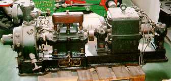
Manufactured by Greenwood and Batley Limited at Albion Works in Leeds, England. It is believed to have been built circa 1900.
Greenwood and Batley Limited donated this DC generator to the University of the Witwatersrand in Johannesburg.
The university donated it to the enthusiasts of the Rand Society of Model Engineers.
In exchange for spare parts for another DC generator, the Rand Society of Model Engineers gave Greenwood and Batley’s DC generator to ESKOM.
This steam turbine driven DC generator is currently on display at Gold Reef City in Johannesburg.
TECHNICAL DESCRIPTION
DC Generator No. 2535 110 Volts 40 Amps 3 000rpm 4 kW
Steam turbine No. G258 3 000rpm Steam pressure 100 psi 7 BHP
Curtis wheel type
COMPRESSED AIR METER
is used in conjunction with a Venturi in the airline.
Compressors at Rosherville Power Station supplied air to a compressed air grid. This grid supplied air to the Central District Gold mines. This meter was located at Rose Deep gold mine.
The meter has a unique air-driven clock.
The meter is on loan to Gold Reef City, Johannesburg. It can be viewed at the entrance to the mine-shaft in this museum and theme park.
PAINTING OF HIGHVELD POWER STATION
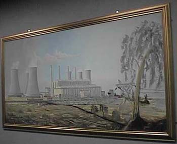
An original oil painting of Highveld Power Station by Hennie Maree.
Hennie Maree worked at ESKOM’s Taaibos Power Station, which was situated nearby.
The size of the painting is 2,5m long x 1,5m wide.
The painting can be viewed at ESKOM, Megawatt Park, Sandton.
TURBINE USED AT SABIE RIVER GORGE HYDRO STATION
This is the remaining turbine of three used at Sabie River Gorge Hydro Power Station. This power station was the first power station designed by engineers employed by the Electricity Supply Commission (ESCOM). The power station was established to supply electrical power to the gold mines in the Sabie district of Mpumalanga (or Eastern Transvaal as it was then known.)
Sabie River Gorge power station operated from 1 April 1928 until it was decommissioned on 5 November 1964.
James Gordon & Company Limited of London manufactured the three turbines in 1925.
TECHNICAL DESCRIPTION
A Francis type turbine and alternator, 450kW 600kVA 750rpm, three-phase, 50 cycles, 3300 volts. The turbine and alternator operated under 64 metres static head of water.
The turbine is on loan to Gold Reef City, Johannesburg. It can be viewed at the mine-shaft in this theme park.

TURBINE USED AT SABIE RIVER GORGE HYDRO STATION
A “RESILIA” PORTABLE TEMPERATURE INDICATOR manufactured by Foster Instrument Company, England. Circa 1945. Using a thermocouple as a sensor, it measured temperature.
Scaled 0 – 7 x 100°C and 0 – 12,9 x 100°F Mirror scale.
Type no. 751 YX/6
Provision is made for the simultaneous connection of 6 thermocouples, any one of which may be selected by key switch. A portable instrument in a wooden case.
Approximate overall dimensions 300 mm x 80 mm x 290 mm.
The indicator is now part of the South African Institute of Electrical Engineers historical collection and can be viewed in Observatory, Johannesburg, South Africa.
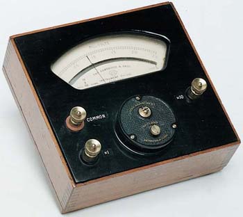
A PORTABLE DC VOLTMETER
Manufactured in England by Cambridge and Paul Instrument Company. Circa 1920 – 1924.
TECHNICAL DESCRIPTION
Portable, dual range, moving coil instrument for voltage measurement up to 25 millivolts DC. Scaled 0 – 2,5 Mirror scale Direct connected Ranges 2,5 and 25 mV
Range selection by terminal connection Resistance 10 and 20 ohms at 20°C
The instrument is housed in a wooden case, Approximate dimensions 185mm x 180mm x 95mm
The voltmeter is now part of the South African Institute of Electrical Engineers historical collection and can be viewed in Observatory, Johannesburg, South Africa.
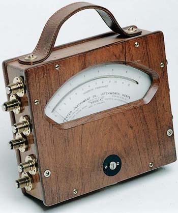
A PORTABLE MULTI-RANGE LABORATORY OHMMETER
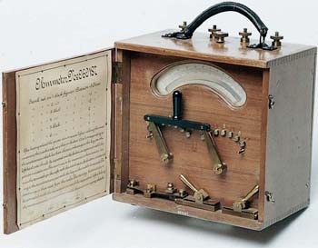
Believed to have been used in 1900. It measured resistance up to 1250 ohms. The manufacturer is unknown.
Scaled 0 – 125 (black) and 125 – 250 (red) Mirror scale
Ranges 0 – 125 ohms, 125 – 250 ohms, 0 – 250 ohms, 250 – 500 ohms, 0 – 625 ohms, 625 – 1250 ohms. Range selection by switches External power supply 5 x 2V storage cells
A portable instrument in wooden case with carrying handle, Approximate overall dimensions 245mm x 150mm x 260mm
Operating instructions inside lid:-
Crank set on – 1: black figures or 2: red figures 1 Division = 5 Ohms
Crank set on – 3: black figures or 4: red figures 1 Division = 2 Ohms
Crank set on – 5: black figures or 6: red figures 1 Division = 1 Ohm