Ankerlig and Gourikwa
Ankerlig (1 327 MW)
The name Ankerlig is derived from an Afrikaans expression, “Om die anker te lig”, which is symbolic of a community that rises above the chains of poverty to experience growth and prosperity.
Construction ofthe first phase commenced in January 2005 and comprised of 4 x 148 MW units which was completed and handed over for commercial operation by June 2007. The second phase comprising of 5 x 147 MW units was declared commercial during February 2009.
The OCGT units are powered by Fuel oil (Diesel). It is intended to supply electricity into the National Grid during peak hours and emergency situations. In addition to its generating capabilities the units are also used to regaulate network voltage fluctuations (SCO – Synchronous Condenser Operation).
The first phase of Ankerlig Gas Turbine Power Station went into commercial operation in 2007, adding 592 MW (4 x 148MW) of capacity to the Peaking Generation group. Started in August 2007, the second phase comprised five additional units with a total capacity of 735 MW (5 x 147 MW). The name “Ankerlig” is symbolic of a community which “rises above the chains of poverty to experience growth and prosperity”.
During 2004 it became apparent that Eskom required a solution, with a very short lead time, in order to have enough electricity to meet the winter peaks of 2007. Open cycle gas turbines (OCGT’s) were chosen as the most viable option as:
- the technology is well tried and tested and readily available
- the units can be erected within a short lead time
- there are numerous suppliers internationally.
Construction began in 2006 and innovative measures to save time and meet challenges saw completion of the project in record time. The combustion engines which drive the turbines are similar to those used in the aviation industry and use a liquid fuel (diesel). The power station, located on the west coast of the Western Cape, is strategically placed should the opportunity to use natural gas arise in the future.
Gourikwa (740 MW )
The first phase of Gourikwa Gas Turbine Power Station went into commercial operation in 2007, adding 444MW (3 x 148MW) of capacity to the Peaking Generation group. Started in August 2007, the second phase comprised two additional units with a total capacity of 296 MW (2 x 148 MW). The name “Gourikwa” refers to the Gourikwa tribe which lives in the area near Mossel Bay, in which the power station is built.
During 2004 it became apparent that Eskom required a solution, with a very short lead time, in order to have enough electricity to meet the winter peaks of 2007. Open cycle gas turbines (OCGT’s) were chosen as the most viable option as:
- the technology is well tried and tested and readily available
- the units can be erected within a short lead time
- there are numerous suppliers internationally (please remove the full stop)
Construction began in 2006 and innovative measures to save time and meet challenges saw completion of the project in record time. The combustion engines which drive the turbines are similar to those used in the aviation industry and use a liquid fuel (diesel). The power station obtains fuel via a pipeline from PetroSA.
OVERVIEW OF THE OCGT POWER STATIONS
History
During 2004 it became apparent that Eskom, as South Africa’s electricity supplier of last resort, required a solution with a very short lead time in order to meet the winter peaks of 2007. After intense investigations, the project that was identified as the most viable was that of the Open cycle Gas Turbines. There are a number of reasons for this.
- The technology has been used extensively all over the world and I readily available
- Stations can be erected, depending on required capacity in a lead time of 1-3 years as opposed to the larger coal and nuclear stations that require 8-10 years lead time.
- This type of technology has a proven track record.
- There are numerous gas turbine suppliers in the world.
Construction phases
The first phase comprised four x 148 MW units with a total sent-out capacity of 592 MW. Construction began in January of 2006 and was completed in record time by June 2007.
Started in August 2007, the second phase comprised five additional units a total capacity of 35 MW. As each machine was completed during late 2007 and early 2009, it was handed over to the Generation Division for commercial operation.
Gourikwa Power Station Unit II
Gourikwa Gas Power Station (total capacity 740 MW)
The first phase comprised three x 148 MW units with a total sent-out capacity of 444 MW, completed in record time in June 207.
Started in September 2007, the second phase comprised to additional units with a combined capacity of 296 MW. The first unit was synchronized to the grid in September 2008, ahead of time and exactly one year to the day after the turning of the first sod of soil. Phases 1 and 2 for Gourikwa will be operated from one combined control room.
Role as peaking power stations
Eskom’s new OCGT (Open Cycle Gas Turbine) power stations are powered by liquid fuel (diesel). They are intended to be used during peak periods and emergency into the Eskom National Grid.
In addition to generating electricity (Generating |Mode), the machines installed during the initial phases of both stations are able to regulate fluctuations in network voltage (SCO – Synchronous Condenser Operation).
Both Ankerlig and Gourikwa Power Stations are part of Peaking Generation, a business unit in the Generation Division Peaks in demand are normally between 06:00 and 08:00 in the morning and 17:00 and 20:00 in the evening. Provision has been made for them to run up fifteen hours a day should this be necessary, albeit at extreme costs.
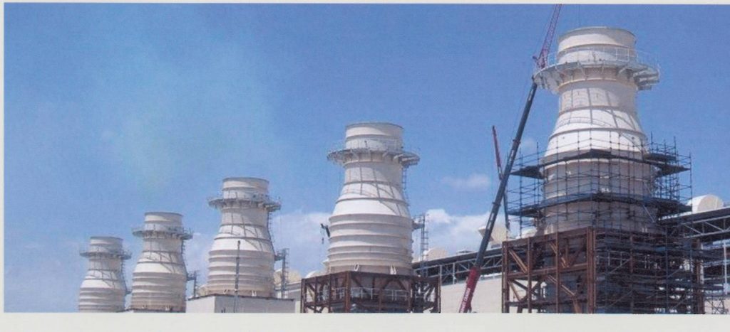

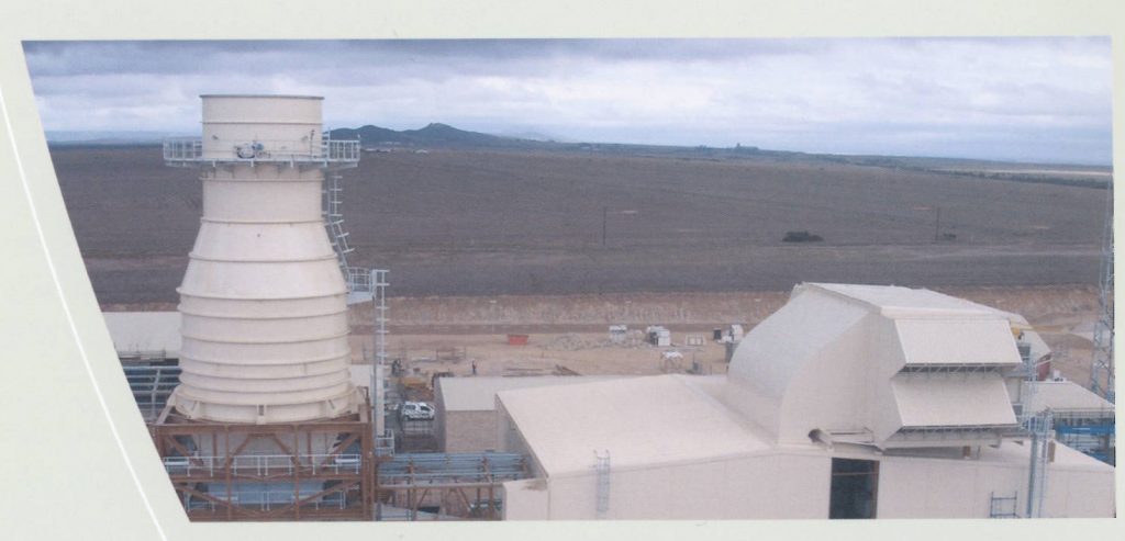
An entire unit occupies an area of approximately 75m x25m with the turbine-generator module erected in a reinforced concrete plinth. The turbine-generator and control units are housed in all-weather, painted steel enclosures.
The five units of Ankerlig Phase 2 are enclosed in a single steel clad turbine hall.

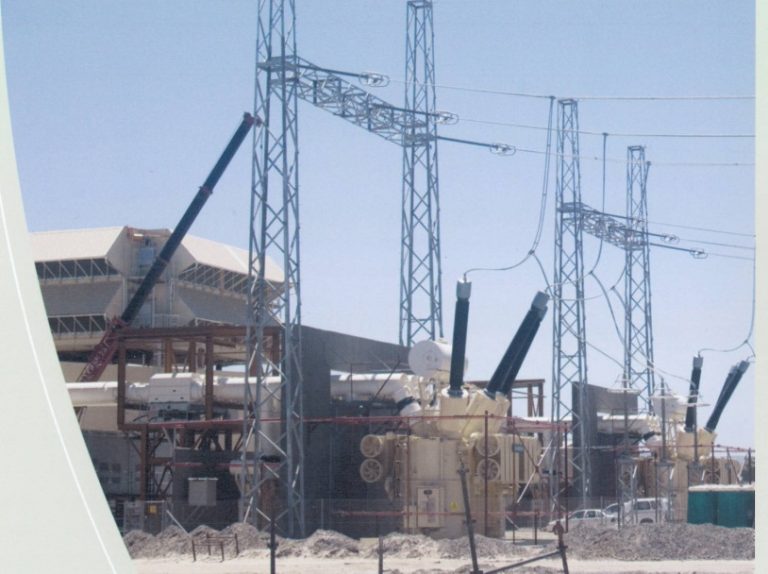
Connection to the national electricity grid
OCGT PRINCIPLES
An OCGT hoes through the same process as any internal combustion engine and as such follows, the Brayton Cycle. The medium used to drive the turbine is gas and for this cycle there are four main states through which air/gas passes in terms of temperature and pressure.
Air enters the system through the filter housing above the unit and into the air intake, which feeds directly into the compressor blades. A suction effect is created by the compression section of the unit. As the air is compressed and moves forward, it creates a low pressure area behind it.
This results in additional air moving into the compression zone. At the same time the air that has already passed through the compressor blades has increased significantly in pressure and slightly in temperature.
The shaft through the unit is continuous. When generating mode is established the rotating turbine blades drive the entire length of the shaft, turning both the compressor blades and the rotor within the generator.
The difference between a combined cycle turbine and an open cycle one is that the hot gas created by the OCGT is simply released into the atmosphere. With a OCGT it is used to heat a boiler which produces steam that drives a turbine/generator set. CCGT’s are more efficient as more power is produced without any additional fuel inputs into the system.
Plant Efficiency and Run-up
The two stations have 14 units between them with a total capacity of 2 067MW. This capacity as well as the efficiency of the units (approximately 34% – 36%) is severely influenced by humidity and ambient temperature as well as pressure. Approximately 30% of total engine power is consumed by the compressor for the purpose of air compression. The stat up process is relatively fast with the units able to synchronize with the grid within 5-7 minutes. The time it takes to reach base load is dependent on which loading rate is used as there are three options. The first is the normal rate of 11 MW min, the second the fast rate to the strain it places on the machines. The total time required therefore ranges between 12-20 minutes to reach full load. The rated speed of the shaft is 50 Hz or 3 000 rpm.
In terms of plant efficiency these units have two fuel modes that fulfil the requirements of the turbines at different stages of operation. The first mode that the fuel system enters during start up is known as diffusion mode. This mode has the advantages of creating a very stable flame and can be used at any output of the machined. The drawbacks are that it is inefficient in terms of fuel consumption and released emissions. Premix mode overcomes these negatives but sacrifices stability to do so. Owing to this, premix can only be used at the upper output ranges of the turbine and a small diffusion flame needs to be maintained, as a pilot light, to ensure the continuity of the premix flame. Diesel is supplied during both of these modes but the difference lies in the fact that the fuel is mixed with air before the combustion zone is premix mode.
Mode Changes
All mode changes go through vey specific steps within the system logic to ensure that all preconditions are adequately met. Modes are Generating, SCO, Turning Gear and Standstill.
Standstill/turning gear to generating
The units are very rarely at complete standstill. When not generating or in the SCO mode they are generally in “turning gear”. The changes from standstill or turning gear modes to generating are very similar.
When a unit starts up, the generator initially acts as a motor, driving the rotor shaft and therefore the compressor/turbine shaft. This function is performed by the static frequency converter. The SFC draws power to drive the shaft, via the start-up transformer, from the medium-voltage supply of the plant auxiliary power supply system.
As the shaft speeds up the turbine also begins to play a role in accelerating the shaft as the compressor blades begin to set up the vacuum effect which assists in driving the machine. While the unit is still at these relatively low speeds, extra lube oil is pumped into the bearings to provide additional lubrication and reduce the frictional forces that the unit experience. When the speed of the unit is between 5.5-6.5 Hz the ignition gas system activates and the gas is ignited by two spark plugs located near each burner. These receive their energy from the ignition transformer. The reason that liquid petroleum gas is used to start up the process rather than diesel is simply due to the fact that liquid petroleum gas is more flammable than diesel and is therefore easier to ignite.

Once the burners are running the turbine begins to play the dominant role in accelerating the shaft. When the shaft reaches approximately 36.5 Hz the ignition transformer is switched off, the ignition gas valves close and diesel is pumped into the burners. The unit now enters diffusion mode. During this mode only some of the fuel is injected into the burners and the rest is returned via the return line to the storage tanks. This means that there is an opportunity to influence the amount of fuel entering the combustion chamber so that the process can be better controlled. The benefit of diffusion mode is that it is very stable over the entire output range of the machine. A negative, however, is that the emission levels are much higher when the machine is run in diffusion mode rather than in premix mode.
The SFC continues to assist in the acceleration of the shaft until it turns at a speed greater the 38.6 Hz. At this point the SFC is shut down and its external isolator is opened. The turbine is now completely responsible for rotating the shaft.
Once the unit is ready to synchronize with the grid the generator breaker closes and the Static Excitation Equipment (SEE) begins to provide energy to the rotor so that the generator can begin to produce power.
Once the unit reaches about 50% of base load and an output temperature greater than 500ºC the unit switches to remix mode. In this mode the fuel enters the burner at a different location which allows it to be mixed with air before the combustion zone. This reduces both the fuel consumption and the emissions
Standstill/turning gear to SCO

In SCO mode the generator is operated as a m1otor to either send out or absorb reactive power from the grid. There are two options by which the generator can be run-up to synchronize with the grid.
The first is to run the unit up using the SFC to a speed greater than 50 Hz. The SFC is then switched off and the machine can synchronize with the grid at the machine slows down naturally. The second method is to run the unit up in the standard manner with the turbine and then disconnect the turbine from the generator one the unit has linked with the grid. The turbine however incurs superfluous from Equivalent Operating Hours (EOH). This mean that maintenance intervals, are reached earlier and required more frequently, which contributes to the running expenses of the unit.
Generation to turning gear/standstill
Before the unit can be completely shut down it is first de-loaded at 11 MW min to a point below an 8 MW output. Once it has reached this level it is further de-loaded until zero MWs are send out. The reason for de-loading in stages is that it allows the other sub-systems on the unit to complete their own shutdown procedure.
When the generator reaches this stage it is disconnected form the grid and the turbine is switched off. The shaft is then allowed to run down naturally until it reaches turning gear speed at which it is rotated for 24 hours to ensure that the shaft and turbine cool down uniformly and that no warping occurs. When the unit is not operating dehumidified air is circulated through both the turbine and the generator to ensure that any corrosion is kept to a minimum. Ambient air is also prevented from entering the turbine while it is not running so that it does not counteract the dehumidifying system.
Emergency trips
Various protection devices are installed to alert the operator to a fault or bring the unit to standstill and prevent damage. Five emergency STOP pushbuttons are installed at appropriate locations to initiate a manual gas turbine trip in the event of an emergency. A gas turbine trip can also be initiated by sensors installed on the unit that monitor temperatures, vibration, pressures, levels and speed. A trip would only be initiated if a specific number of sensors indicate a fault. This makes provision for a faulty reading and to prevent unnecessary trips.
Measuring environmental impact
The Central Emission Monitoring System (CEMS) on each unit measures the carbon monoxide (CO), nitrous oxide (NOx) and oxygen (O2) emissions. The quality of other hazardous gases that may be present, such as sulphur dioxide (SO2) can be calculated from the chemical composition of the fuel. The reason why the amount of oxygen present is determined is to verify whether or not ambient air has been added to the sample to reduce the concentration of the other gases. Samples are only taken once a unit has been running for one minute. This is to ensure that any debris in the exhaust stack is released and does not affet the accuracy and credibility of the results.
TECHNICAL DATA – MAIN PLANT SYSTEMS
Lube oil system
The Lube Oil System has four main functions. First it, provides lubricating oil to the bearings along the shaft so as to minimize the friction within, and to remove heat from, the bearings. The lube oil is continually circulated within the system and also ensures that any wear debris or solid contaminants are flushed from the bearings.
Second the lube oil is sprayed onto a single-stage hydraulic turbine which is connected to the gas turbine shaft by gearings. This enables the shaft to turn at approximately 2Hz or 120 rpm at Turning Gear or Barring Speed. This is an important function as it is vital that the shaft is rotated at this speed for 24 hours after being in either Synchronous Condenser Operation (SCO) or generation mode to ensure that the turbine cools down uniformly so that the shaft does not wrap.
Third, the Lube Oil System is used to jack the shaft up slightly when the unit is first activated after being at either a very low speed or standstill. The jacking oil is necessary as at these low speeds, the lube oil in the bearings is not sufficient to create an adequate hydrodynamic lubricating film. The presence of the jacking oil, therefore helps to further reduce the friction in the bearings, ensuring that the inertia of the shaft can be overcome with less force being required.
Fourth lube oil is used by the synchronous condenser clutch to operate its locking control and output brake.
Lube oil cooling system
The lube oil cooling is completed in two stages. The lube oil itself is water cooled through the plate-type heat exchangers that can be found on top of the lube oil skid. This water in turn air cooled via three fin fan coolers which release the heat into the atmosphere. The system is a closed system, meaning that no additional water is required unless a leak occurs. This system uses demineralised water to ensure that the system is maintained in as new a condition as possible.
Fuel oil system
The Fuel Oil System links the Fuel Forwarding System to the turbine to provide the burners within the combustion chambers with fuel oil as well as to remove any fuel that is not burnt. The fuel enters that system at a pressure of between 4 and 7 bar, although it is generally maintained above 6 Bar. The fuel is passed through a 10 micron duplex filter before entering the injection pump to remove any debris that could influence the system. The injection pump is a 16-stage centrifugal pump which increases the pressure of the fuel to approximately 80 Bar which is required for atomization to take place in the burners. There are three different fuel lines going to and leaving the combustion chambers, namely the diffusion supply and return lines and the premix supply line. Each of these lines has a control calve which ensures that the correct amount of fuel is being injected into the burners.
The Fuel Oil System thus comprises the fuel injection pump, duplex filters and the fuel lines. It also has a fuel oil leakage tank to collect any fuel from the various drain and relief lines in the system.
Purge water system
The Purge Water System uses demineralised (demin) water from the forced reverse osmosis plant on site. The system supplies demin, water at the required pressure to the premix burners whenever the unit changes from diffusion to remix mode or vice versa. The reason for this flushing is first to cool off the premix burners before use and then to clean the burners afterwards. This prevents coking and ensures that the nozzles stay clear. The length of each flush on start-up Diffusion-Premix mode lasts 10 seconds and uses 37.5 litres of water. On shutdown, the Premix-Diffusion Mode Flush for 20 seconds and uses 75 litres of water.
Hydraulic system
The Hydraulic System provides pressurized hydraulic fluid for the operation of the position actuators in the auxiliary systems. Predominant of these are the control valves o the Fuel Oil System. The condition of the hydraulic oil is very important and must remain within the ISO 4406 specifications. For this reason the oil is filtered continuously.
Ignition gas system
The Ignition Gas System is responsible for the storage of the ignition gas as well as supplying the gas to the combustion chambers. The gas used on site is 90-97% propane and is contained in two 6.5m³ tanks a pressure of 9-15 bar. The tanks are, however, only filled to 60% of their capacity.
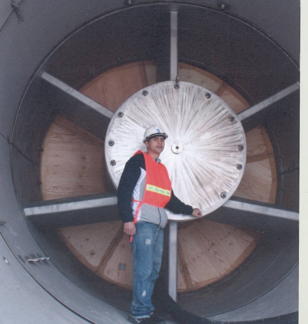
Filter housing
The air enters the unit through the filter housing situated on the top of the unit. The filter house includes weather hoods, bird screens, pre- and fine filters. The measurement for these filters is 25 microns and 4 microns respectively. The air enters the housing from three sides after which it is fed through silences into the air intake and then into the compressor.
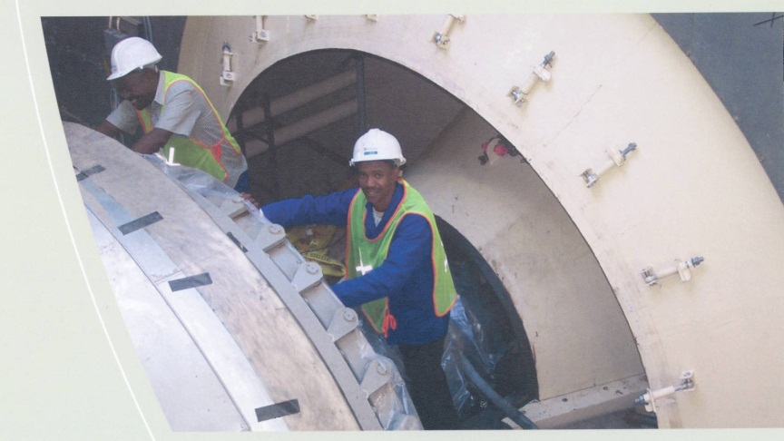
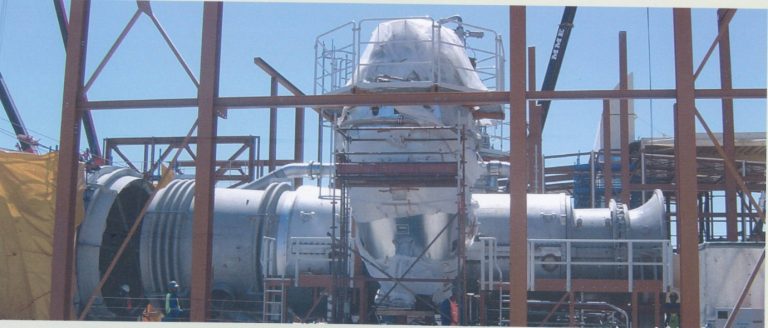
Turbine
The turbine is viewed as the portion of the unit that incorporates the air intake, compressor section combustion chambers, turbine section and diffuser. It is 9.45m long and 4.1m in diameter. The compressor section has 16 stages and converts mechanical energy into the kinetic and potential energy of the compressed air. The combustion chambers are silo type cambers and are found on either side of the turbine, weighing approximately 6 tons each. There are eight individual hybrid burners per chamber and both the liquid petroleum (LP) gas and fuel are fed into the same burner although at differ locations. The flame cylinder at the top of each combustion chamber is covered with ceramic tiles, similar to those of space shuttles to protect the structure from the heat as the temperature ranges from 1 030ºC to 1 200ºC. There are four sets of turbine blades after which the air passes through to the exhaust. The turbine also incorporates three blow-off pipes which bleed air from the compressor stages and release it via the exhaust to prevent surging in the turbine during start up.
Generator
The generator is the heaviest single component, on site, weighing 223 tons. This component was transported from the North of Germany via Rotterdam in the Netherlands, through the Suez Canal and down the coast of Africa. The generator has a rated output of 15.75 kV and 6 818A at 3 000 rpm with a power factor of 0.8.
The rotor conductors are made of copper with a silver content of approximately 0.1%. This combination increases the strength at higher temperatures to eliminate coil deformation due to thermal stresses. The insulation between the individual turns is made of layers of glass fibre laminate. The field winding consists of several coils connected in series and inserted into the longitudinal slots of the rotor body. The coils are electrically connected in series so that one north and one south magnetic pole are obtained.
Generator cooling system
The generators are not 100% efficient in excess of 2 000 kW being produced in the form of heat. The generators are equipped with indirectly air cooled stator windings and a radial direct air cooled rotor winding. The cooling air for the generator is drawn by axial-flow fans arranged on the rotor via lateral openings in the stator housing. The heat generated in the generator interior is dissipated through air. The rotor is directly air-cooled with heat losses being transmitted directly from the winding cooper to the cooling air. Cooling air is supplied at a rate of 50m³/s at 28º.
Electrical features
For export onto the national grid, the generator-motor output of 15.75 kV is stepped up to 400 kV by a generator transformer. Each unit has a generator transformer rated at 186 MVA operating at 50 Hz. These transformers have a mass of about 135 tons and are filled with 55 tons of oil. They are cooled using an Oil Direct Air Forced (ODAF) cooling system. Various other voltages are required on site and from the 15.75 kV Generator output a unit auxiliary transformer steps the voltage down to 6.6 kV for the unit boards.
In the event that either the generator or auxiliary transformer fails, the unit boards can be interconnected to get a supply from other units. The 66 kV system supplies a fuel injection pump.
Backup diesel generators are available to supply all 6.6 kV boards in the event that power from the grid is lost. Their main purpose is to supply energy to essential systems needed to start the gas turbines or to ensure a safe shutdown if power to the gas turbine is lost. All the transformers, boards and interconnections are controlled and protected by motor operated circuit breakers.
Exhaust

The exhaust stack transfers the hot air from the turbine and releases it into the atmosphere at a maximum temperature of 560ºC. The stack is 30m high and has a diameter of approximately 10 m. The exhaust has a mass flow rate of around 520 kg/s and a velocity of approximately 40 m/s.
TECHNICAL DATA – BALANCED OF PLANT SYSTEMS
Fuel off-loading system
Ankerlig
As Ankerlig has no direct pipeline to a fuel depot the fuel is brought in via petrol tanker and of-loaded at one of the off-loading skids at a rate of between 1 300 – 1 400 litres/min.


TECHNICAL DATA
ANKLERLIG
ANKERLIG | |
Number of units | 9 |
Output per unit | |
Phase 1 | 148 MW |
Phase 2 | 147 MW |
Total output | 1 327 MW |
GOURIKWA | |
Number of units | 5 |
Output per unit | 148 MW |
Total Output | 740 MW |
Synchronizing time | 5-7 minutes |
Foundation concrete per power Island | 1998 m³ |
Reinforcement per power island | 107 ton |
TRANSFORMERS | |
GENERATOR TRANSFORMER | |
Tranformer rating | 186 MVA |
Operating frequency | 50 Hz |
Transformer mass | 135 ton |
Tranformer oil mass | 55 ton |
Voltage ratio (kV) | 420 / 15.75 |
Cooling | Oil Direct Air Forced (ODAF) |
UNIT AUXILIARY TRANSFORMER | |
Transformer rating: | 12 MVA |
Operating frequency | 50 Hz |
Transformer mass | 22.5 ton |
Transformer oil mass | 4.5 ton |
Voltage ratio (kV) | 15.75 / 6.93 |
Cooling | Oil Natural Air Natural (ONAN) |
Transformer rating | 740 kVA |
Operating frequency | 50 Hz |
Voltage ratio (kV) | 6.6 / 0.420 |
Cooling | Air Natural (AN) |
LUBE OIL SYSTEM | |
Barring speed | 120 rpm |
Lube oil reservoir capacity | 56 000 litres |
Pump capacity | 164 m³/h at Bar |
96 m³/h at 5.5 Bar | |
45 dm³/min at 160 Bar | |
Jacking oil pump capacity – filter type | 20 micron duplex filter |
PURGE WATER SYSTEM | |
Flush length | 10 seconds |
Water usage per flush | 80 – 100 litres |
Ignition gas system | |
GAS | 90 – 97% Propane |
Ignition has mass flow | 0.13 kg/s |
Ignition gas required per ignition | 19 kg |
Min. ignition gas supply pressure | 9 Bar |
Max. ignition gas supply pressure | 15 Bar |
Ignition gas tank material | P355NH |
Ignition gas tank corrosion allowance | 3 mm |
Tank capacity | 6.5 m³ |
| FILTER HOUSING | |
Air filter sizes | 25 micron, 4 micron |
TURBINE | |
Turbine type | Siemens V94.2 |
Turbine weight | 196 ton |
Turbine length | 9.45 m |
Turbine diameter | 4.1 m |
Number of stages in turbine compressor | 16 |
Combustion chamber weight | approx. 6 ton |
Number of burners per combustion chamber | 8 |
Combustion chamber temperature | 1 030ᵒC – 1 200ᵒC |
Foundation concrete per turbine | 496 m³ |
Weight of reinforcement | 81 ton |
Piling depth | 6.1 m |
EXHAUST | |
Maximum temperature | 560ᵒC |
Exhaust stack height | 30 m |
Exhaust diameter | 10 m |
Exhaust has mass flow rate: | 520 kg/s |
Exhaust gas velocity: | 40 m/s |
GENERATOR | |
Output – Voltage | 15.75 kV± 5% |
Current | 6 818 A |
Speed | 3 000 rpm |
Frequency | 50 Hz |
Power factor | 0.8 |
Direction of rotation | Anti – clockwise |
(View from generator to turbine) | |
Number of poles | 2 |
Weight | 223 ton |
Moment of inertia | 7006 kgm² |
(Rotor complete) | |
Break away torque | 2 |
– with pressure oil | 273 Nm |
– without pressure oil | 22.7 Nm |
Bearing losses per bearing | 90 kW |
GENERATOR COOLING SYSTEM | |
Heat Losses | 2 000 kW |
Cooling air supply oil | 50 m³/s |
Cooling air temperature | 28ᵒC |
FUEL SYSTEM | |
FUEL OFF-LOADING SYSTEM | |
ANKERLIG | |
Off loading method | Tankers 4 off-loading skids Phase 1) |
Tankers 5 off-loading skids Phase 2) |
Supply rate | 1 300 – 1 400 litres/min |
GOURIKWA | |
Off-loading method | Direct pipeline |
Tankers 3 off-loading skids Phase 1) | |
Tankers 2 off-loading skids Phase 2) | |
SUPPLY RATE | |
– Tankers – Pipeline Pipeline length Pipeline diameter | 1 300 – 1 400 litres/min 3 000 litres/min Approximately 4.2 km 200 mm |
FUEL STORAGE TANKS: ANKERLIG | |
Fuel storage tank capacity | 2 x 2.7 million litres (Phase 1) |
| 1 x 5.4 million litres (Phase 2) | |
2 x 2.7 million litres (Phase 2) | |
Fuel storage tanks: GOURIKWA | |
Fuel storage tank capacity | 4 x 2.7 million litres |
Fuel treatment system | |
Fuel treatment output | 50 m³/s |
Fuel forwarding system | |
Fuel forwarding pressure | 4 – 7 Bar |
VSD speed | 2 900 rpm |
VSD output flow rate | 284 m³/hr |
Filter sizes | 30 -micron, 5 micron |
Fuel injection system | |
Pump type | 16-stage centrifugal pump |
Output pressure | 80 Bar |
Fire fighting system |
System pressure | 600-700 kPa |
Reverse osmosis plant | |
Production rate | 1m³/hr |
Conductivity | 0.5µS/cm |
Storage tank size | 15m³ |

