Duvha Power Station
Brief History
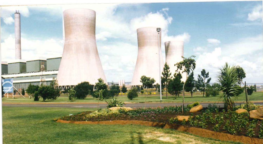
During the seventies the demand for electricity in South Africa increased at an average of nine percent per year. In response to this demand, Dr Straszacker the chairman said, ESCOM had to virtually double its generating capacity. Against this background, construction of Duvha power station started in November 1975 on a farm called Speekfontein just outside Witbank. Duvha was one of South Africa’s largest fossil fired power stations, and was often referred to as the “flagship” of the ESCOM fleet. The combined generating capacity of the six units is 3 600 MW, enough power to supply a city three times the size of Johannesburg with electricity on a winter’s night. Duvha is a base load plant. This means it operates around the clock to help meet South Africa’s electricity requirements. The demand for Duvha’s electricity is determined by the National Control Centre, according to system requirements, plant availability and other strategic factors. The availability of coal and water makes this area ideally suited for the establishment of power stations. Hence, this region is better known as the Power House of South Africa. When Duvha was completed the smoke stacks were the tallest freestanding concrete structures in the Southern Hemisphere each 300 metres tall (July 1992). Margaret Rawics was responsible for the landscape planning and design of the site.
Mpumalanga, previously known as Eastern Transvaal, means “Where the sun rises” Symbolically Duvha, the Venda word for the sun, can be seen as the heart of this region and is not only generating electricity, but indicates ‘light’ to the people of this country. Duvha power station ascribes to the ESCOM vision to “provide the lowest-cost electricity the world for growth and prosperity and fully support the ESCOM Generation priorities.
Dates on which the units went into Commercial Service
Unit 1 went into commercial service on 18 August 1980, Unit 2 on 1 October 1980, Unit 3 on 16 September 1981, Unit 4 on 1 July 1982, Unit 5 on 31 March 1983 and Unit 6 on 22 February 1984. Project costs totaled T1,6 billion over that eight-year period. Something significant about these dates is that the planned commercial loads were to be 12 months apart, but due to demand the interval between units four and five was reduced to nine months, which in itself was an achievement.
The last of Duvha’s six 600 MW units were taken into commercial operation in February 1984. Project costs totalled R1,6 billion over that eight-year period.
Power Station Managers
Duvha has had six Power Station Managers to date namely: Don Burger , Ross Hatton, Colin Marsh, Louis Nel, Ehud Matya (the first black power station manager in ESCOM and Brian Dames to date.
Duvha and its involvement in the Community
Duvha is involved in the education of children from the area by providing assistance to the Duvha Primary School and Hanga Secondary School located near the power station.
Duvha Primary School was established in 1982 with the power station developing available facilities.
In 1992 Hanga Secondary School also opened its doors. Duvha continued to support these schools – largely towards transportation of school children.
Duvha also contributed to the development of small businesses and therefore supported job creation and economic growth. Facilities at the Ikagne single quarters were converted into little shops. Identified entrepreneurs were empowered to run their businesses and currently there is a total of six shops, a shoe repair and leather workshop, a general dealer, welding shop, a tailor, a dressmaker and a dry cleaning service
Integration with the local community was one of the 1996 goals and several interventions took place of which one was a clean up day at four schools in Witbank.
Interesting Events
In Duvha’s short history it has experienced many interesting events.
The Duvha AmaZulu dancers attended an international Eistedford in France in July 1989. If you have ever watched the AmaZulu’s dancing, you will recall how captivating the dance is. As they pound their drums and rustle their animal skins, one is drawn closer to their history. The Duvha AmaZulus have performed at many other popular venues such as Gold Reef City, the CSIR and at various shows. It was the team spirit and enthusiasm that motivated their trip to France – it was with great pleasure that Duvha sent these men to France to be, not only ambassadors for Eskom, but South Africa at large.
In 1986 a baboon got past the security gates in a very mysterious way. A security guard spotted the baboon first. The baboon very calmly, walked to the gate and the security guards couldn’t believe their eyes. This created a fair amount of chaos as the baboon was chased. After searching for a day the baboon was found trapped between unit 5 and 6. The inevitable had happed since the baboon was dangerous and bewildered. To this day his origin is still unknown.
Another interesting event at Duvha occurred in 1988 when Protective Services personnel found a big mole snake at the gate. They caught the snake and another employee, who was doing research on mole snakes, let it fee in safer surroundings.
Brief description of Plant
Control
Each of Duvha’s six boiler-turbine sets is run as a separate entity, with its own controls and instrumentation incorporated into its own control desks and panels. There are three control rooms, each serving a pair of sets. Here the operators’ can execute every major task associated with start-up, normal operation, shutdown and emergency operation. The operators are in permanent contact with other ESCOM control centres that make up the integrated transmission network. A data-logging computer continuously monitors the main operating and alarm systems, and provides a constant flow of information on video screens and printers.
Coal Supply
Crushed coal, smaller than 25 mm is delivered from the neighbouring Duvha Opencast Mine, the largest opencast coal mine in the Southern Hemisphere. Duvha’s opencast mine was started in 1976, and is now capable of supplying just over 10 million tons of coal a year. Reserves will last for more than 30 years at that rate of production. A 4,5 km conveyor belt to form a single energy unit links the power station and the colliery. Delivery to the plant is at the rate of 845 000 tons a month, and the two staithes have capacities of 55 000 and 110 000 tons respectively. In addition a stockpile of 500 000 tons is maintained. From the staiths, coal is fed to the boiler bunkers, of which there are six per boiler. Each bunker has a capacity of 670 tons, which means there is sufficient storage capacity at the boilers for 12 hours operation at full load. When a furnace is started up, fuel oil is used until the combustion of the pulverised coal is stable. At Duvha, two storage tanks are used for fuel oil, with a combined capacity of 3 000 tons.
Following on behind the strip mining, the spoil piles are flattened, covered in topsoil and fertilised, and then replanted with various types of grass, trees and shrubs. A nursery has been established for the restoration programme.
A project has been established whereby the life of the coal reserves for use by Duvha power station has been extended to ± 40 years. The project entails the washing and blending of coal obtained from three different mines namely: Douglas, Middelburg and Wolwekrans.
Long term benefits of this project include the utilization of coal reserves from these mines as well as a consistent supply of a better quality blended coal to the power station. A new coal sampling plant was commissioned before the commencement of the new coal supply agreement between ESCOM and Ingwe early in 1995
Mills
Coal from the boiler bunkers is fed under control into the mills, the feed rate being determined by the requirements for steam. Inside the mills either large steel balls or rollers run in circular tracks, to pulverise the coal to powder. This fine, highly combustible powder is blown from each mill into the boilers at some 63 tons an hour. There are six mills to each boiler, providing a spare capacity of two mills per boiler when coal of design quality is being burned. At full capacity, each boiler requires between 250 and 300 tons of coal an hour, depending on the calorific value of the coal.
Boilers

The six boilers are of the Benson type, which depends on forced circulation and has no steam drum. The feedwater, which is highly purified and demineralised, makes one continuous and uninterrupted circuit through boiler, turbine, condenser, and boiler again. On its path through the boiler, the feedwater evaporates and as more heat is absorbed, the steam becomes superheated to a temperature of 540° C and a pressure of 17,1 MPa.
A feature of the steam pipework is a high-pressure system that allows the superheated steam to bypass the high-pressure turbine when necessary, to flow directly into the reheat pipe work. From there, it bypasses the intermediate pressure and low pressure turbines and flows into the main condenser. This system means that the boiler can be operated independently of the turbine and the correct steam temperature and pressure can be obtained before the generator is started up. Also, if a turbine trips, the system allows the boiler to be operated at roughly 40 per cent of its maximum load, ready for a rapid restart; and, if a turbine sheds a large part of its load, the turbine can be run at a low load while the boiler is maintained at a higher load. In both instances, the boiler is maintained at a higher load. In both instances, the bypass system prevents, within the limits of its capacity, sudden pressure rises from exceeding the settings of the safety valves in the re-heater.
Each boiler is fitted with 24 burners arranged in six rows of two in each of the front and rear walls of the furnace. Each coal mill supplies four burners – two in the front wall and tow in the rear wall. Mounted in the centre of each burner is an oil burner, and these are used for starting up and for stabilising the combustion of coal at low loads.
Forced draught fans supply secondary air to the burner windboxes while primary air fans transport pulverised coal from the mills to the burners. Combustion gases are drawn from the furnace, by two induced draught fans, over the surfaces of the steam superheater, the re-heaters, the economiser, and air preheaters, through the electrostatic precipitators and into the chimney. The precipitators collect more than 99 per cent of the dust, or fly ash.
Each boiler has a capacity of 507 kg/s of steam, and the feedwater is supplied, at a pressure of 22 Mpa, by two electric pumps rated at 13 MW each or one steam-driven pump. At maximum continuous rating the efficiency of the boilers is 93,9 per cent. The total mass of one boiler and its supporting structure is 9 800 tons, and its water content, when cold, is 185 tons. The volume of the furnace is approximately 13 000 m².
Fabric Filter Plants (Unit 1,2 and 3)
This plant replaces the precipitators for Units 1,2 and 3 and consists of an ABB fläkt Optipulse pulsejet fabric filter, utilising acrylic dralon T bags. The filter is divided into four isolatable compartments. Each compartment contains a total of 6 724 bags, each eight metres long, giving a total of 26 896 bags per boiler. The plant is designed to handle 1 290 cubic metres of boiler gas per second, which gives a filter velocity of 90,015 metres/sec.
TURBINES
There are six turbines at Duvha power station, manufactured by GEC Turbo-Generators of Rugby in the United Kingdom. Each turbine unit has high-pressure and intermediate pressure cylinders and twin double-flow low-pressure cylinders. The high pressure and intermediate pressure cylinders are constructed with an internal and external casing to allow for fast starting up and rapid variation in load. Foundations and supports for one turbine include 8 000 m³ or 20 000 tons of concrete.
FEED HEATING PLANT
The condensate temperature in the condenser hotwell is about 37°C. In order to obtain maximum system efficiency it is necessary to reheat the condensate before returning it to the boiler. To achieve this, the condensate is passed through numerous heaters before feeding it into the boiler. All the heaters are of the surface type in which the water flows through tube nests. Steam extracted from different stages of the turbine heats the water by conduction through the tube metal.
A de-aerator, situated between the low- and high-pressure heaters, removes entrained oxygen in the condenstate and heats the water through direct contact with steam extracted from the turbines. The condenstate is pumped from the condenser to the deaerator through the low-pressure heaters by means of the main condensate extraction pumps. The condensate is then pumped from the de-aerator feedwater tank to the boiler through the high-pressure heaters by the boiler feedpumps. The final feedwater temperature at 600 MW is 247ºC.
CONDENSERS
The condensers are of the dual-pressure, surface type. The vacuum inside the condensers is established by steamjet air ejectors and maintained in normal operation by waterjet air ejectors. The steam exhausted from the low-pressure cylinder condenses over 22 552 brass tubes, which have a surface area totalling 23 400m². Each boiler-turbine set has a condenser with a heat exchange capacity of approximately 400 MW.
GENERATORS
Each generator is rated at 667 MVA, and produces 600 MW at full load. The sent-out capacity is 575 MW, the difference of 25 MW being used to run the auxiliary equipment of the turbine and boiler plant. Generator cooling is achieved through two systems. The stator and rotor are cooled by hydrogen at a pressure of 400kPa, which is circulated through water coolers of the surface type. Circulation of the hydrogen is by two fans that are locked to the rotor shaft. The circulation of demineralised water-cools the stator windings and core. The generators operate at 22 kV, and their output is transformed to 400 kV for distribution via the national grid.
CHIMNEYS
Duvha’s two chimneys are the tallest freestanding concrete structures in the Southern Hemisphere, at 300 m each. Each chimney contains three flues, so that there is one flue per boiler. The diameter of the chimneys at the base is 22m, and both are on 60 piles of 1,2 m by 18m. Approximately 40 000 tons of concrete was used in the construction of each stack.

COOLING TOWERS
The six cooling towers at Duvha are designed for a total thermal load of nearly 19 000 GJ/h. The three larger towers are 149 m in height and 114 m in diameter at the base. The minimum shell thickness is 180 mm. At full load, the evaporation from one tower amounts to 30 Ml a day.
WATER SUPPLY
Duvha’s water requirements can be met from either of two sources. First, water can be pumped from the Vygeboom and Nooitgedacht Dams in Mpumalanga, which are fed by the Komati River. These dams can also be supplied with water from the Usutu system. Secondly, water can be obtained from the Witbank Dam in the upper reaches of the Olifants River and supplemented with water from the Grootdraai Dam in the Vaal River near Standerton.
The second source is used as little as possible because it is not as clean as the Komati River. Clean water is highly desirable, since purification and demineralisation costs are proportional to the concentration of material that has to be removed. This second source is only used if the Komati system cannot supply the water.
| TECHNICAL DATA | |
| Generating capacity | 3600 MW |
| Operating | 3 shifts of 70 in 24 hours |
| FUEL | |
| Mining company | Ingwe Group |
| Calorific value | 23,32 MJ/kg (dry basis) |
| Ash content | 28,85 per cent (dry basis) |
| Total annual consumption | 10 135 000 tons |
| Coal staithe capacity No 1 No 2 |
110 000 tons 55 000 tons |
| Boiler bunker capacity | 24 120 tons |
| Coal consumed at full load | 1 500-1 800 tons per hour |
|
MILLING PLANT
Sets 1-4 |
|
| Manufacturer | Babcock & Willcox (SA) |
| Type | Vertical spindle (ball & ring) |
| Number | 6 per boiler |
| Speed | 26 r/min |
| Rated output | 66 tons/hour |
|
Sets 5 and 6
|
|
| Manufacturer | Loesche |
| Type | Vertical spindle (roller type) |
| Number | 6 per boiler |
| Speed | 36 r/min |
| Rated output | 66 tons/hour |
|
BOILERS
|
|
| Manufacturer | SteinMüller(Africa)(Pty)Ltd |
| Type | Benson |
| Number | 6 |
| Maximum continuous rating | 17,1 MPa |
| Final steam teperature | 540oC |
| Reheater steam pressure | 39,1 MPa |
| Reheater steam temperature | 540oC |
| Number of burners | 24 |
| Height (roof of hopper) | 94,0 m |
| Width at burner level | 20,2 m |
| Depth at buner level | 17,2 m |
| Boiler expansion (downwards) | 340 mm |
| Approximate volume | 13 080 m3 |
|
BAG FILTERS (Unit 1,2 and 3)
|
|
| Manufacturer | ABB Power Tech |
| Control temperature inlet | 126,5oC max & 120oC min |
| Differential Pressure | 2,3 kPa |
| Filter velocity | 0,015 m/sec |
| System control | Siemens S135 PLC |
| Effective cloth area | 86 170 m2 |
| Stack emission | 50 mg/sm3 |
|
ELECTROSTATIC PRECIPITATORS
|
|
| Manufacturer | Lurgi SA |
| Control gas temperature | 150oC |
| Operating volume | 2 000 0 0 m3/h |
| CO2 content | 41 mbar |
| Gas dust load (inlet) | 30 g/m3 |
| Clean gas dust load | 120 mg/m3 |
|
TURBINES
|
|
| Manufacturer | GEC Turbine Generators(Pty) Ltd |
| Type | Multi-cylinder impulse-reaction |
| Rating (Generator output) | 600 MW |
| Speed | 3000 r/min |
| Superheated steam pressure, HP stopvalve inlet |
16,1 MPa (abs) |
| Superheated steam temperature, HP stopvalve inlet |
535oC |
| Steam pressure, HP outlet | 4 MPa (abs) |
| Steam temperature, HP outlet | 332oC |
| Reheated steam pressure, IP inlet | 3,75 MPa (abs) |
| Reheated steam temperature, IP inlet |
535oC |
| Steam pressure, IP outlet | 0,42 MPa (abs) |
| Steam temperature, IP outlet | 252oC |
| Steam pressure inside condenser | 8 kPa (abs) |
| Average teperature inside condenser | 37oC |
| Heat consumption (MCR) | 8 220 KJ/kWh |
| Steam Flow | 520 kg/s |
|
GENERATORS
|
|
| Manufacturer | GEC Turbine Generators(Pty) Ltd |
| Rated capacity | 600 MW (maximum continuous output) |
| Terminal voltage | 22 kV (50 Hz) |
| Power factor | 0,9 (lagging) |
| Cooling medium | Hydrogen at 400 kPa |
|
GENERATOR-TRANSFORMERS
|
|
| Manufacturer | ASEA Electric (SA) Ltd |
| Rated capacity | 700 MVA |
| Terminal voltage: Primary | 22 kV |
| Terminal voltage: Secondary | 420 Kv |
|
COOLING TOWERS
|
|
| Number | 6 |
| Type | Hyperbolic natural draught |
| Overall dimensions | Sets 1-3 Sets 4-6 |
| Height | 180 mm 180 mm |
| Nominal flow rate/ct | 45 000 m3/h 48 800 m3/h |
| Temperature-in | 39,44oC 34,7oC |
| Temperature-out | 22,5oC 19,2oC |
| Evaporation at duty point | 1 270 m3/h 1 270 m3/h |
| Nominal heat rejection | 886 MW 886 MW |
| Maximum guaranteed heat Rejection |
1 275 MW 1 275 MW |
| Number | 12 |
| Total capacity | 78 m3/s |
|
CHIMNEYS
|
|
| Number (3 flues each) | 2 |
| Height | 300 m |
| Wundshield diameter (base) | 22 m |
|
MAIN CONTRACTORS
|
|
| Earthworks | Grinaker Construction (Pty) Ltd |
| Civil Engineering | LTA Construction |
| Steelwork (subcontractor) | Dorbyl Ltd |
| Boilers | Steinmuller (Africa) (Pty) Ltd |
| Turbines | GEC Turbine Generators (Pty) Ltd |
| Generator transformers | ASEA Electric (SA) Ltd |
| Cooling towers | Hamon Sobelco (with LTA Construction as civil subcontractor) |
| Chimney 1 | Monanhan and Frost (Pty) Ltd |
| Chimney 2 | Murray and Roberts (Transvaal) (Pty) (Ltd) |
| Cabling | Huberts Davies (Pty) Ltd |
| Instrumentation | Siemens Ltd |
| Process computers | Honeywell |
| Fire Control System | Mather and Platt (Pty) Ltd |
| Coal handling (staithes) | High Structures (Pty) Ltd |
| Conveyers | Spencer Melksham (Pty) Ltd |
| Ash Plants 1-3 | DB Thermal |
| Ash Plants 4-6 | Steinmuller Africa (Pty) Ltd |
| Construction water ring | Hall Longmore & Company |
| Cooling water pumps 1-3 | Amalgamated Power Engineering (SA) (Pty) Ltd |
| Cooling water pumps 4-6 | Sulzer Bros. (SA) Ltd |
| Sewage plant | Satec Hudamec |
| Fabric filer Plants 1-3 |
ABB |
| Electrostatic precipitators | Lurgi (SA) (Pty) Ltd |
| Water treatment plant | Foster Wheeler |
|
Bibliography
Duvha Coal-fired giant – Technical information Brochure
ESCOM News Megawatt Magazines ESCOM Annual reports Duvha internal Newsletter |
Interviews
Martinus Biemons
Technical Support Services Manager Duvha Power Station |