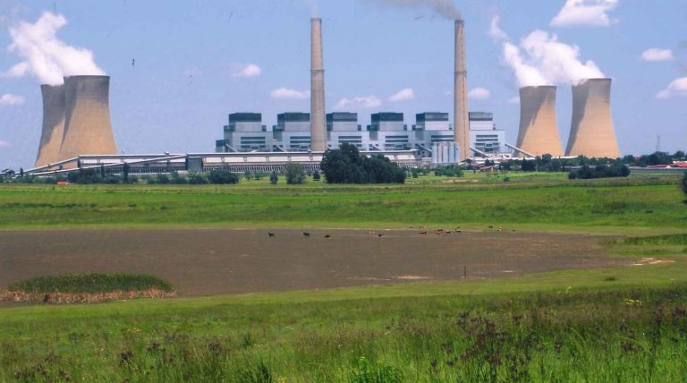
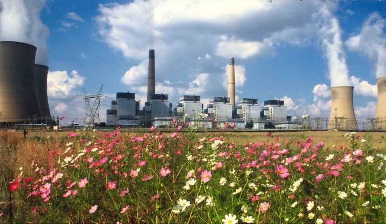
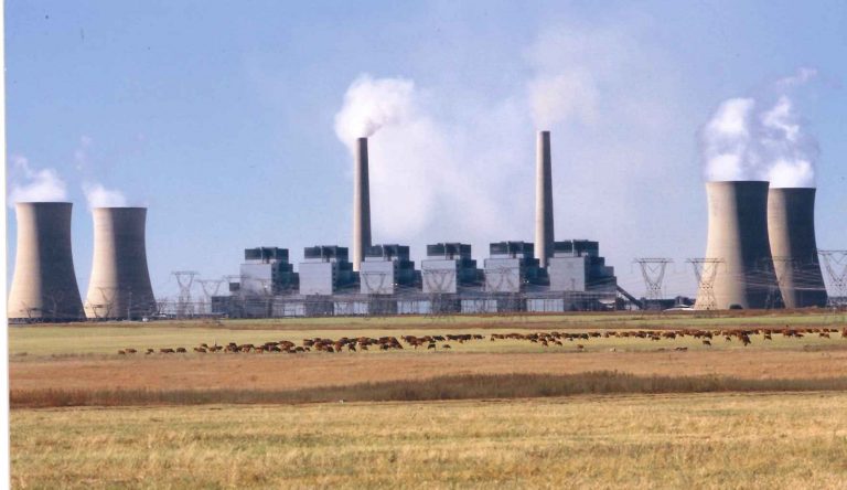
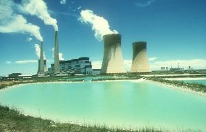
Kriel Power Station
All operations for normal, cold, warm or hot start-up loading and d-loading and normal shutdown of the power plant are conducted from the unit control room in manual, or partially or fully automatic, modes as required for each functional group. The analogue control system provides fully automatic load control of the whole unit and facilities for set point of subgroups as well as manual control of each drive. Similarly, binary control provides fully automatic run-up of the major plant groups plus a facility for individual drive control. In the event of the failure of running auxiliaries standby plant is automatically switched on. If main plant groups fail, the unit automatically runs back to the highest possible safe state. Data-logging computers continuously monitor the main operating and alarm systems and provide a constant flow of information on video screens and printers.
Fuel Handling
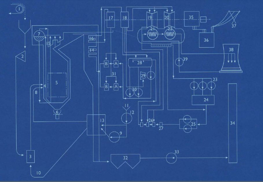
The grinding elements consist of a stationary upper grinding ring fitted with hydraulic tension rams, and 240ºC) to repeat the cycle .a lower rotating grinding ring fitted with hydraulic tension rams, and a lower rotating grinding ring spun at 32,8 r/min by a 3,3 kV GEC electrical motor through a reduction gearbox. The 11 coal grinding balls run in tracks between the upper and lower grinding rings. They are hollow spheres made from a special wear-resistant steel and have a diameter of 768 mm. The grinding elements of the 12.0E mills are constructed in the same way. However, they have only 10 grinding balls with a diameter of 930 mm, a rotation speed of 26.8 r/min and a maximum grinding capacity of 60 t/h. The pulverised coal is transported from the mill by means of primary air. r/min, and that of units 4 to 6 is 650 kW at 1 485 r/min
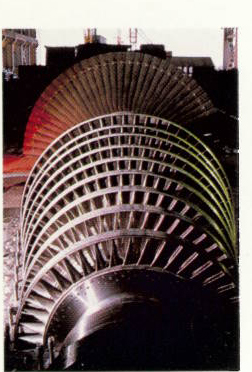
The exhaust steam is returned to the re heater part of the boiler, where its temperature is raised to 516ºC at a pressure of about 3,2 MPa (abs). It enters the IP cylinder via the interceptor and throttle valves at 510º and 3,16 MPa (abs). Entering at the centre of the IP cylinder, the steam flows outwards and horizontally to the shaft in both directions, through 15 fixed and 15 moving blades. The IP turbine exhausts steam now enters the two LP double-flow cylinders at a pressure of 431 kPa (abs) and a temperature of 245ºC. The steam flows through 12 moving and 12 stationary blades on each side of the Alp rotor into the condenser. Steam exhausts from the LP cylinder at 40ºC and 7,7 kPa (abs).
Kriel Circuit Diagram
TECHNICAL DATA
Generating capacity | 6 x 500 MW – 3000 MW |
Fuel | |
Mining company | Amcoal |
Calorific value | |
(underground coal) | 23.4 MJ/kg (dry basis) |
(opencast coal) | 18.2-20.4 MJ/kg (dry basis) |
Ash content | |
(underground coal) | 23.4% (dry basis) |
Sulphur content | |
(underground coal) | ±1% (dry basis) |
(opencast coal) | ±1% (dry basis) |
Coal consumed at full load | ±1 400 tons/h |
Total annual consumption | ±8-9 million tons |
Coal staithe capacity | 120 620 tons |
Staithe 1 | 72 000 tons |
Staithe 2 | 48 620 tons |
Stockpile capacity | 1,7 million tons |
Boiler bunker capacity | 19 900 tons per unit |
Fuel oil | Waxy |
Storage capacity | 1 350 tons |
Annual consumption (total) | ±4 000 kl |
Mills | |
Manufacturer | Babcock & Wilcox (SA) |
Type | Medium-speed, vertical-spindle |
Number | 6 per unit |
Model | 10.8E – Unit 1-3 12.0E – 4-6 |
Rotational speed | 10.8E – 32.8 r/min 12.0E – 26.8 r/min |
Rated output | 10.8E – 47.8 tons/h 12.9E – 60 tons/h |
Feeders | |
Manufacturer | Stock Equipment |
Number | 6 per unit |
Minimum coal | 22.5 tons/h Units 1-3 27.9 tons/h Units 4-6 |
Maximum coal | 50.76 tons/h Units 1-3 57.07 tons/h Units 4-6 |
Through put control | Variable-speed 380V DC motors |
Induced-draught Fans | |
Manufacturer | Davidson & Co Ltd |
Type | Bab 141A double-inlet impreller |
Number | 2 per boiler |
Volume flow per boiler (design) | 1 030 m³/s /Units 1-3 10162 m³/s/Units 4-6 |
Mass flow per boiler (design) |
Generating capacity | 6 x 500 MW – 3000 MW |
Fuel | |
Mining company | Amcoal |
Calorific value | |
(underground coal) | 23.4 MJ/kg (dry basis) |
(opencast coal) | 18.2-20.4 MJ/kg (dry basis) |
Ash content | |
(underground coal) | 23.4% (dry basis) |
Sulphur content | |
(underground coal) | ±1% (dry basis) |
(opencast coal) | ±1% (dry basis) |
Coal consumed at full load | ±1 400 tons/h |
Total annual consumption | ±8-9 million tons |
Coal staithe capacity | 120 620 tons |
Staithe 1 | 72 000 tons |
Staithe 2 | 48 620 tons |
Stockpile capacity | 1,7 million tons |
Boiler bunker capacity | 19 900 tons per unit |
Fuel oil | Waxy |
Storage capacity | 1 350 tons |
Annual consumption (total) | ±4 000 kl |
Mills | |
Manufacturer | Babcock & Wilcox (SA) |
Type | Medium-speed, vertical-spindle |
Number | 6 per unit |
Model | 10.8E – Unit 1-3 12.0E – 4-6 |
Rotational speed | 10.8E – 32.8r/min 12.0E – 26.8 r/min |
Rated output | 10.8E – 47.8 tons/h 12.9E – 60 tons/h |
Feeders | |
Manufacturer | Stock Equipment |
Number | 6 per unit |
Minimum coal throughput | 22.5 tons/h Units 1-3 27.9 tons/h Units 4-6 |
Maximum coal throughput | 50.76 tons/h Units 1-3 57.07 tons/h Units 4-6 |
Throughput control | Variable-speed |
Induced-draught Fans | |
Manufacturer | Davidson & Co Ltd |
Type | Bab 141A double-inlet impreller |
Number | 2 per boiler |
Volume flow per boiler (design) | 1 030 m³/s /Units 1-3 10162 m³/s/Units 4-6 |
Mass flow per boiler (design) | 745 kg/s Units 1-3 778 kg/s Units 4-6 |
Impeller shaft coupling | Bibby |
Motor output | 2 360 kW Units 1-3 2 500 kW Units 4-6 |
Motor speed | 596 r/min |
Air control method | CS-vane |
Chimneys | |
Number | 2 |
Height | 213 m |
Diameter (base) | 23.8 m |
Diameter (top) ID | 13.8 m |
Foundation | 93 piles of 1 220 mm diameter |
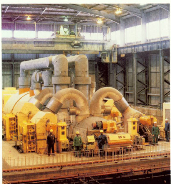
Turbines | |
Manufacturer | Brown Boveri/CEM |
Type | Multi-cylinder impulse reaction |
Rating (generator output) | 550 MVA |
Speed | 3 000 r/min |
Steam flow to HP turbine | 415.7 kg/s at MCR |
HP exhaust steam flow to RH | 381.3 kg/s |
Work rate of HP cylinder | 33.85% or 146.2 MW |
HP cylinder blading efficiency | 90.9% |
Steam flow to IP turbine | 394.6 kg/s at MCR |
Work rate of IP cylinder | 37.64% or 192.4 MW |
IP cylinder blading efficiency | 92.2% |
Steam flow to LP 1 | 162.5 kg/s |
Steam flow to LP 2 | 159.8 kg/s |
Work rate of LP 1 & 2 | 28.51% or 174.7 MW |
LP cylinder efficiency | 86.69% |
Total work of turbine train | 513.1 MW |
Total efficiency | 98.15% |
Condenser | |
Type | Dual-pressure surface |
Cooling principle | Conduction |
Type and number of tubes | 26 000 admiralty brass |
Total tube surface area | 23 520 m² |
Condenser pressure | 7.7 kPa (abs) |
Condenser steam pressure | 40ºC |
Condenser steam flow | 280.7 kg/s |
Extraction pumps | |
Motor manufacturer | GEC |
Type | 3.3 kV induction |
Power output | 1 500 kW |
Speed | 1 488 r/min |
Pump manufacturer | Sulzer |
Type | Multistage |
First stage | Single impeller |
Delivery pressure | 650 kPa |
Second stage | 4 impellers |
Delivery pressure | 650 kPa |
Second stage | 4 impellers |
Delivery pressure | 3 800 kPa |
Condensate at 25ºC | |
pH | 8.5-9 |
Dissolved O₂ | 90-150 |
Oil | Not detectable µg/l |
CO₂ | Not detectable µg/l |
SiO₂ | 5 µg/max |
Fe | 3 µ/l max |
Low pressure Feed Heaters | |
Bled steam temperature | No 1, 68ºC No 2, 86ºC No 3, 157ºC No 4, 245ºC |
Water inlet temperature | No 1, 40ºC
|
Water outlet temperature | No 1, 66ºC No 2, 84ºC No 3, 112ºC No 4, 141ºC |
Steam safety valve | No 3, 686 kPa No 4, 686 kPa |
Water safety valves | No 1- 4, 4 000 kPa |
De-aerator | |
Steam pressure | 800 kPa |
Safety valve | 1 100 kPa |
Water temperature | 176ºC |
Feed-water After De-aerator | |
Dissolved O₂ | 90-150 µg/1max |
Boiler Feed Pumps (electric) | |
Manufacturer | Sulzer |
Number | 2 per unit |
Type | Multistage |
Discharge capacity | 241 kg/s |
Discharge pressure | 26.8 MPa (abs) |
Motor power output | 10 000 kW |
Motor speed | 1 492 r/min |
Main pump speed | 6 826 r/min |
Flow rate control | Regulating valve |
PA Fans | |
Manufacturer | Howden SA Fan Co |
Number | 6 per unit |
Fabricated from | Boiler quality steel |
Assembly | Welded to impeller shaft |
Type | Single inlet type |
Coupling | Wellman Bibby |
Motor | 3.3 kV squirrel cage induction |
Motor output | 465 kW Units 1-3 650 kW Units 4-6 |
Motor speed | 1 486 r/min Units 1 485 r/min |
Fan delivery | 150-250ºC |
Fan delivery | 5-10 kPa |
Pulverised-Fuel | |
Number | 36 per unit |
Fuel oil Burners | |
Number | 36 per unit |
Delivery capacity | 305 kg/h |
Boilers | |
Manufacturer
| Steinmuller |
Type | 6 |
Number Maximum | 440 kg/s |
Final steam | 17.2 MPa |
Final steam | 516ºC |
Re heater steam | 3.42 MPa |
Re heater steam
| 516ºC |
Height (roof to | 71.3 m |
Width at burner | 23.5 m |
Depth at burner | 14.17 m |
Boiler expansion | 300 mm |
Boiler water | 168 300 kg |
Furnace volume | ±10 856 m³ |
Total heating | 67 639 m² |
Boiler | |
Manaufacturer | KSB |
Number | 1 per boiler |
Type | Wet winding |
Rated capacity | 200 kg/s |
Power | 850 kW |
Speed | 2 950 r/min |
Voltage | 3.3 kV |
Re Heaters | |
Type | 7 245 m², Re 3 645 m², Re |
Heat absorption | 13.64 kJ/m²/s Re 26.72 kJ/m²/s Re |
Protection | 4 safety valves |
Total discharge | 498 kg/s |
Super heaters | |
Number | 3 per boiler |
Type | Convective |
Heating surfaces | 4 330 m². 3 545 m² 2 700 m² |
Heat absorption | 28.3 kJ/m²/s |
Protection | 4 safety valves |
Total discharge capacity | 440 kg/s |
Economiser | |
Type | Gilled tube |
Heating surface | 37 994 m² |
Heat absorption | 4.6 kJ/m²s |
Air Pre heaters | |
Type | Davidson regenerative |
Number | 2 per boiler |
Total heating surface | 65 840 m² |
Rotation speed | ±25 r/min |
Motor power | 18.5 kW |
Total heat | 1.85 kJ/m²s |
Precipitators | |
Manufacturer | Brandt Engineering |
Type | Electrostatic, ((with SO₂ pre-treatment) |
Number | 2 per boiler |
Number of passes | 4 |
Number of fields | 3 – Units 1-3 4 – Units 4-6 |
Flue gas dust concentration at inlet | 12.27 g/Am³ – 14.28 g/Am³ – |
Flue gas dust concentration at outlet | 41.54 mg/Am³ – 17.00 mg/Am3 – |
Overall collecting efficiency | 99.65% – Units 99.88% – Units |
Forced Draught Fans | |
Manufacturer | Davidson & Co Ltd |
Type | Bab 92 A |
Number | 2 per boiler |
Volume flow per boiler (design) | 714 m³/s – Units 745 m³/s – Units |
Mass flow per boiler (design) | 667 kg/s – Units 696 kg/s – Units |
Motor speed | 745 r/min |
Air control method | Vane inlet control system |
Boiler Feed Pumps (turbine driven) | |
Manufacturer | Sulzer |
Type | Multistage |
Number | 1 per unit |
Discharge capacity | 482 kg/s |
Discharge pressure | 25.8 MPs (abs) |
Turbine speed | 4 500 r/min at full load |
Main pump speed | Turbine speed |
Flow rate control | Turbine speed |
High pressure Feed Heaters | |
6A & 6B steam safety valve | 2.5 MPa |
Water inlet temperature | 178ºC |
Water outlet temperature | 207ºC |
Bled steam temperature | ±431ºC |
Bled steam pressure | ±1.8 MPa |
7A & 7B steam safety valve | 5.0 MPa |
Water outlet temperature | 240ºC |
Steam inlet temperature | 297ºC |
Steam inlet pressure | 3.4 MPa |
Water safety pressure for all HP heaters | 25 Mpa |
Cold-water System | |
Motor manufacturer | Mitsubishi |
Type | 3.3 kV squirrel-cage screen protected |
Rated Power | 1 491 kW |
Motor poles | 18 |
Pump | Vertical mixed flow, centrifugal, concrete volute |
Discharge capacity | 5.65 m³s |
Speed | 328 r/min |
Pump power consumption | 1 400 kW |
Suction branch bore at impeller | 1 150 mm |
Discharge branch bore at impeller | 1 500 mm |
Impeller | Stainless steel BS 3100 |
Cooling Towers | |
Number | 4 |
Type | Concrete construction natural draught |
Height | 136 m |
Diameter at base ring beam | 91.38 m |
Pond diameter | 100 m |
Depth of pond | 1.8 m |
Capacity of tower pond | 12 176 m³ |
Throat diameter | 58.3 m |
Diameter at the top | 63.47 m |
Air inlet area | 2 317 m² |
Number of vertical piles supporting shell | 36 |
Height of vertical piles | 1.9 m |
Quantity of air at specified barometric passing through tower when cooling 9.32m³ water/s under following conditions: | |
Circulating flow rate | 12.3 kg/s |
Cooling range | 16,719 m³/s |
Re cooled water temperature | 24ºC |
Atmospheric dry bulb temperature | 15.45ºC |
Atmospheric wet bulb temperature | 11.05ºC |
Relative humidity | 61.4% |
Mean atmospheric pressure | 84.7 kPa |
Circulating Water | |
pH | 8.4 |
Total alkalinity | 120 mg/l (max) |
Hardness | 400 mg/l |
Generators | |
Manufacturer | CEM/BBC |
Rated capacity | 555 MVA |
Terminal voltage | 18 kV (50 Hz) |
Power factor | 0.9 (lagging) |
Cooling medium rotor | Hydrogen at 400 kPa |
Cooling medium stator | De mineralised water |
Total efficiency of generators | 98.15% |
Water and Effluent | |
Total raw water consumption | 150 Ml/day |
Cooling water | 90 Ml/day |
Potable water production | 9 Ml/day |
De mineralised water production | 8.6 Ml/day |
Main Contractors | |
Boilers | L&C Steinmuller (Africa) (Pty) Ltd |
Precipitators | Brandt Engineering |
Turbines | Brown Boveri/CIE, Electro Mecanique (CEM) |
Generator transformers | ASEA Electric (SA) Ltd |
Cooling towers | Monohan & Frost |
Cooling water pumps and boiler feed pumps | Sulzer Bros (SA) Ltd |
Chimneys | Monohan & Frost |
Cabling and switchgear | Hubert Davies Construction (Pty) Ltd |
Instrumentation and control | Siemens AG c/o |
Process computers | Leeds & Northrup |
Low pressure services | Stewarts & Lloyds Ltd |
Fire control system | Mather & Platt (SA) (Pty) Ltd |
Coal and ash conveyors | Spencer (Melksham) SA (Pty) Ltd |
Water treatment plant | D H Harris Ltd |
Coal silos and civil works | CMGM Glybeton & Monasiebou |