Kendal Power Station
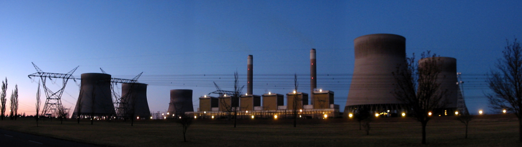
Kendal Power Station Kendal - the largest indirect dry-cooled power station in the world was offically opened on 25 October 1994.
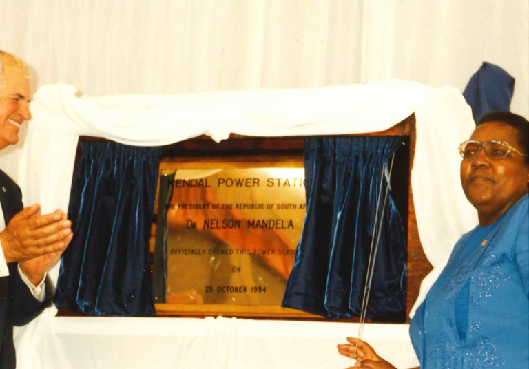
Construction commenced on Kendal Power Station in July 1982. On completion in 1993 it became the world’s largest indirect dry-cooled power station. The largest direct dry-cooled power station at the time was Matimba near Ellisras. Eskom has conducted successful long-term trials of dry-cooling technology on smaller plant at two sites. Indirect cooling has been tested at Grootvlei power station on the two 200 MW sets, and direct cooling on the 4 x 30 MW sets at SWAWEK’s Van Eck power station in Namibia. A small, 160 direct cooled, system is in operation in Utrillos, Spain, but the only other large direct dry-cooled scheme from which data could be drawn is the 265 MW unit at Wyodak in the United States. Both Kendal and Matimba are designed to generate approximately 4 000 MW. In opting to apply both the direct and indirect dry-cooled systems on this scale
Eskom is pioneering development in the field of dry-cooling technology.
Kendal power station is located 40 km west of Witbank in Mpumalanga. Construction started in July 1982 and the last of its six 686 MW units went into full operation in 1983. Though there are abundant coal resources in the Mpumalanga Province, the requirements of the three largest wet-cooled power stations in this area – Kriel, Matla and Duvha had already placed strain on water supplies. Limited water resources and the consequent rising cost of water were the major consideration that influenced Eskom’s decision to enter the field of dry cooling technology.
The total station water consumption of a dry-cooled system does not exceed 0,2lkWh, compared with the 2,5lkWh consumed by wet-cooled systems. Evaporation losses in wet-cooled systems account for approximately 80% of the water requirements of a conventional wet-cooled power station. On the South African highveld these losses can amount to 1,2 million litres an hour per 600 MW cooling tower. The station consists of six 686 MW turbo-generator units. Kendal is fired with coal having a calorific value of 17,5-21,0 Mj/kg and an ash content of about 32% to 40% mined in the Bombardie Cologne coalfield. Twin overland conveyors transport the coal from the mine through the stock-yard into the coalbunkers.
With an installed capacity of 4 116 MW, Kendal is currently the largest coal-fired power station in the world. Construction started in 1982 and the last of its six 686 MW units went into full operation in 1993. Kendal’s power is fed into the 400 kV network
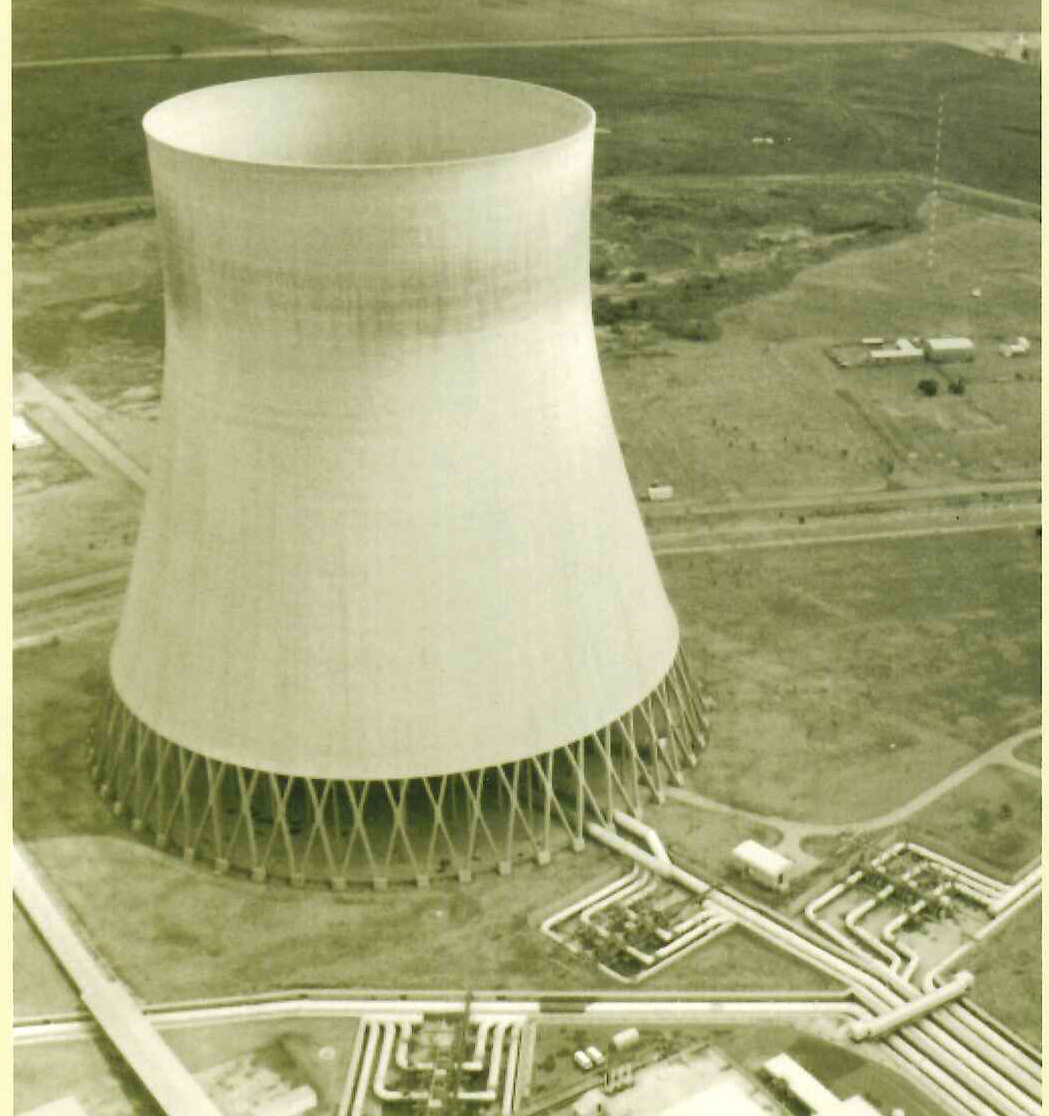
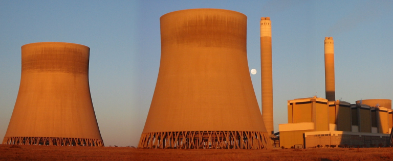
Kendal has an indirect dry-cooling system, which means that it uses significantly less water in its cooling process than the conventional wet-cooled power stations. The average water consumption at Kendal is 0,1 litre per kWh produced. The station’s cooling towers are the largest structures of their kind in the world, with a height and base diameter of 165 m.
Fuel and Water
Though there are abundant coal resources in the Mpumalanga Province, the requirements of the three largest wet-cooled power stations in this area – Kriel, Matla and Duvha – have already placed strain on water supplies. Limited water resources and the consequent rising cost of water were the major considerations that influenced Eskom’s decision to enter the field of dry-cooling technology. The total station water consumption of a dry-cooled system does not exceed 0.2 l/kWh, compared with the 2.5 l/kWh consumed by wet-cooled systems. Evaporation losses in wet-cooled systems account for approximately 80% of the water requirements of a conventional wet-cooled power station. On the South African Highveld these losses can amount to 1.2 million litres an hour per 600 MW cooling tower. Kendal power station, sited approximately 40 km west of Witbank, consists of six 686 MW turbo-generator units. Kendal is fired with coal having a calorific value of 17.5-21.0 Mj/kg and an ash content of about 32% to 40% mined in the Bombardie Cologne coalfield.Twin overland conveyors transport the coal form the mine through the stock-year into the coalbunkers.
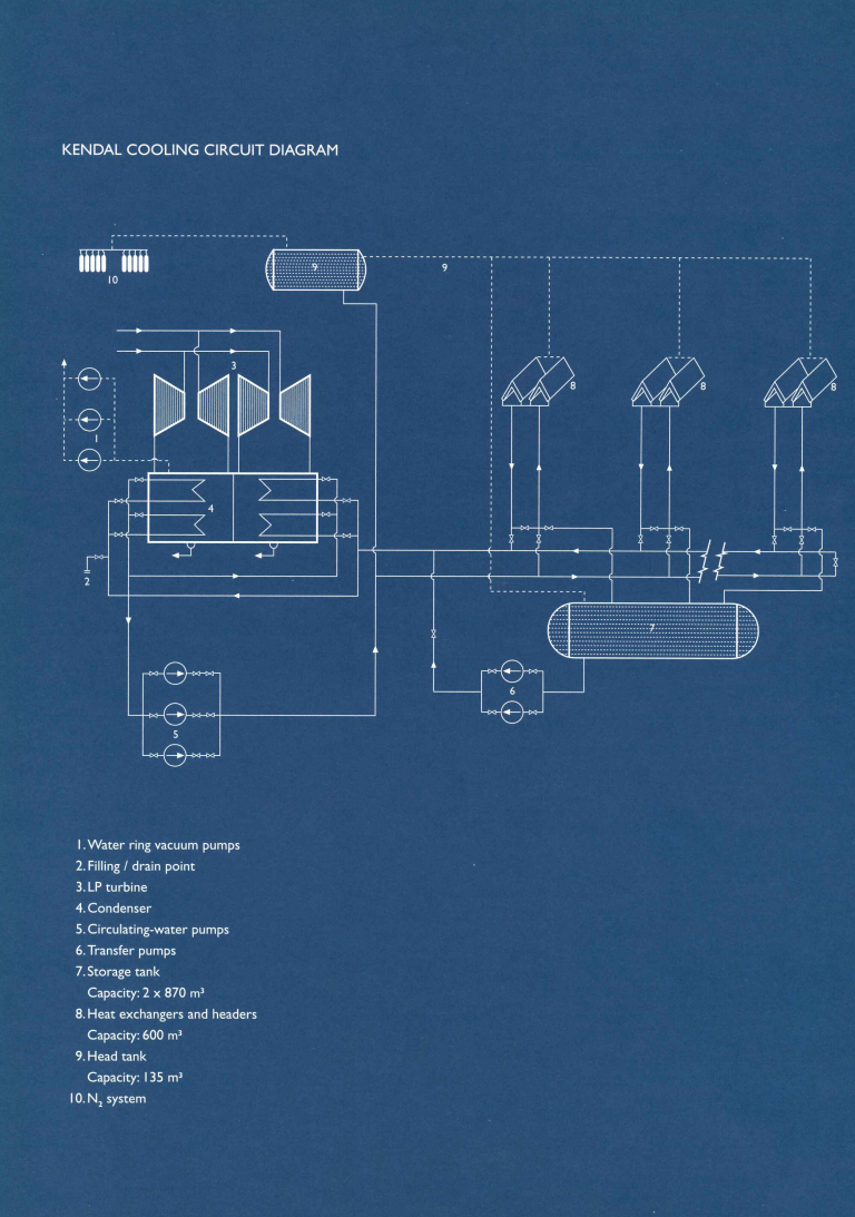
Kendal cooling circuit
For each unit there is one cooling water system, including the cooling tower with its tuber bundle heat exchangers, three circulating pumps (units 4 to 6) two circulating pumps), one hot and one cold duct and a condenser. The circulating water cools the condensate in the condenser, but never comes into contact with it. Once it has cooled the condensate the circulating water is pumped to the cooling tower along the hot duct. It is then cooled in the tube bundle heat exchangers by the natural draught created within the cooling tower. The circulating water is then returned to the condenser via the cold duct, thus completing the circuit.
Kendal the basic cycle
Fuel and combustion
Coal crushed to a nominal top size of 35 mm is fed from the stockyard to the 1 000 t bunkers of which there are five for each boiler, providing a storage capacity of eight hours at full load. From the bunker outlets the coal is fed into five double-ended tube ball mills, where it is ground to a very fine powder. A draught of hot air blows the pulverised coal into the furnace via the pulverised-fuel burners. Forced-draught fans add secondary air for combustion. An oil burner is incorporated at each paid of pulverised fuel burners for combustion support below 40% load and for initial light up. Each boiler has a coal burning rate of 350 t/h. The coal combustion produces coarse and fly ash in a ratio of 1.5. The coarse ash drops to the bottom of the boiler and is conveyed to the ash dump. Fly ash is carried in the flue gases to the electrostatic precipitators. Before entering the precipitators, the flue gas is conditioned by injecting minute quantities of sulphur trioxide gas, which enables an ash removal efficiency of 99.9% to be achieved. The ash is collected in the precipitator hoppers. From here a chain conveyor system is carries it to the fly ash bunker, where it is moistened to facilitate transport, and then removed to the ash dump on the overland conveyor. Induced-draught fans draw the cleaned flue gases from the precipitators to be discharged into the atmosphere via the chimney.
Steam circuit
The water circulating inside the tubing which forms the boiler furnace walls absorbs heat produced by the burning pulverised coal in the boiler. The maximum continuous rating of each boiler at the super-heater outlet is 577 kg/s with a super-heated steam temperature and pressure of 540ºC and 17.24 MPa respectively. The super-heated steam is fed to the high-pressure turbine, where it expands, causing the turbine to rotate at 3 000 r/min. After exhausting some of its energy in the high-pressure turbine, the steam is reheated in the boiler re-heater and passed through the intermediate-pressure turbine an then to the two low-pressure turbines.
Cooling and reticulation
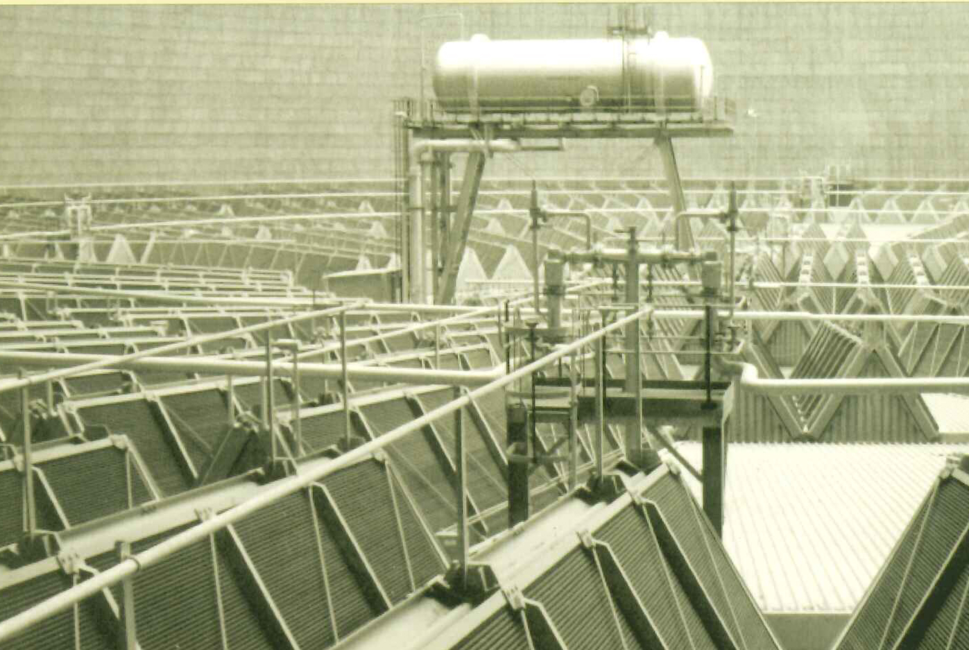
Exhaust steam from the low-pressure turbine is condensed in a twin surface condenser, comprising of about 45 0-00 small-diameter tubes through which cooling water passes. The condensate is collected in the hot-well below the condenser and withdrawn by extraction pumps. From here, after being polished by a condensate polishing plant, it is pumped back to the boiler through a feed-heating system. The cooling water, which flows through the tubes of the surface condenser, absorbs the heat from the steam. Circulating pumps ensure a continuous flow of cooling water though the condenser tubes and cooling tower elements. The water flows through large diameter steel ducts to the cooling tower, which is essentially a two pass cross counter flow heat exchanger made up of A-frame bundles of cooling elements. These galvanised steel finned tubes cooling elements are tubes to which external fins have been attached to increase the rate at which heat is transferred to the air. The A-frame bundles are arranged in concentric rings within the tower. The hot water from the condenser flows into the tube bundles and as cooling air passes over the external surface of the finned tubes, it removes the heat from the water. Natural convection draughts provide a constant flow of cooling air. The cooling towers are the largest structures of their kind in the world, with a height of 165 m and a base diameter of 165 m. The cooled water flows through down-comers from the tube bundles and is conveyed back to the surface condenser by large-diameter steel ducts.
The water used in the cooling circuit is demineralised water to which hydrazine has been added. The hydrazine reacts with any free oxygen to produce water and free nitrogen, thus inhibiting corrosion. The system will not normally require make-up water. However, connections are provided to the station’s demineralised water supply so that the system can be charged and topped up if required. As the volume of the water in the cooling circuit changes with the temperature it is not possible to achieve a completely closed system. To minimize the ingress of oxygen as much as possible a nitrogen blanketing system is used. This supplies nitrogen at a pressure of 2 kPa to the free surface of the water in the head tank and storage tanks as well as in the headers of the cooling bundles.
Kendal plant
Control
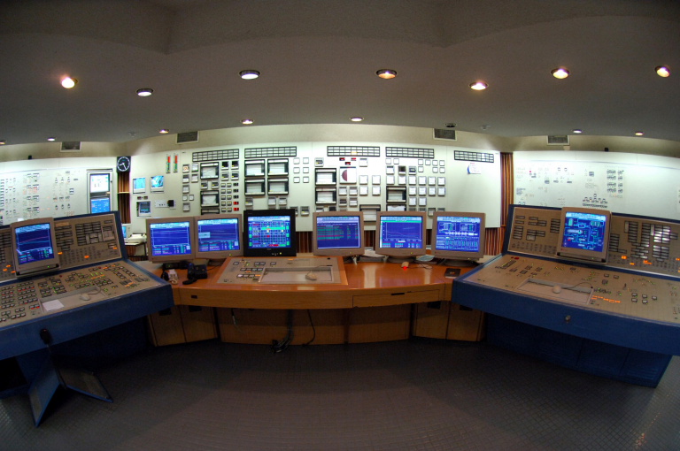
Each pf Kendal’s six boiler-turbine set is operated as a separate unit from its own unit control room.A separate central control desk with panel is dedicated to the operation of each single unit. Auto/manual control stations provide full control of all units and extensive use is made of computer graphics which provide live mimics on video screens. The entire process is monitored and controlled by a distributed micro-processor-based control system. For other Eskom coal-fired 600 MW power plants, several hundred kilometres of signal cable and more than 35 000 marshalling links with a total wire length of over 250 km are required to transmit and process and analogue and binary control signals from the plant. The system at Kendal reduces the amount of signal cable and offers increased flexibility to make modifications to the system.
Boilers
The boilers are of the controlled circulation sub-critical design with coal-fired radiant furnaces and reheating. The combustion chamber has a membrane wall design with no division wall. The upper third of the combustion chamber contains the pendant elements of super-heaters and re heaters. Boiler feed water is heated to a temperature of 247ºC. The water/steam mixture from the radiant furnace tubes is collected in a steam drum. From here steam flows through the low-temperature pendant super-heaters, the super-heated radiant wall tubes and further to the pendant super-heaters. Its temperature is increased to 540ºC at a pressure of 17.24 MPa. The super-heated steam is then passed to the high-pressure cylinder of the turbine, entering at a pressure of 16.1 MPa. The conditions of the steam leaving the high-pressure section of the turbine are 4.07 MPa and 313ºC. From here the steam is returned to the re-heater section of the boiler, where it reaches a temperature of 540ºC at 3.89 MPa before being led to the intermediate-pressure turbine. A high-pressure bypass system allows the superheated steam to bypass the high-pressure turbine when necessary so that it flows directly into the re heat pipework. From there it can bypass the intermediate-pressure and low-pressure turbines into the main condenser. This enables the boiler to be operated independently of the turbines and correct steam temperatures and pressure to be obtained before the turbo-generator is started up. Should a turbine trip, the system allows the boiler to be operated at roughly 50% of its maximum, load, ready for a rapid restart, resulting in a saving of fuel oil. Should a turbine shed a large part of its load, it can be run at a low load while the boiler is maintained at a higher load as in the case of a unit maintaining its own house load / islanding load, ready for a rapid restart, resulting in a saving of fuel oil. Should a turbine shed a large part of its load, it can be run at a load-load while the boiler is maintained at a higher load, as in the case of a unit maintaining its own house /load islanding load. In both cases, the bypass system prevents sudden pressure rises from exceeding the settings of the safety valves in the re-heaters and super-heater. The maximum steam flow is 577 kg/s.
Boiler feed pumps
Each unit at Kendal is supplied with three boiler feed pumps. Each of these pumps is driven by an 8 MW variable-speed electric motor. Each pump is capable of supplying 50% of the required water flow to the boiler during full-load operation. In emergencies a pump can deliver 429 litres of water a second at a speed of 5 861 r/min. Each boiler feed pump train consists of a booster pump, gearbox, variable-speed motor and a main pump.
Milling plant
There are five tube ball mills per boiler at Kendal. These are rated to grind 103 t/h of raw coal The pulverised fuel product delivered is very fine, with 99% being less than 300 microns in size. The mills are charged with 893 t of balls of about 50 mm in diameter and draw approximately 1 600 kW of power. Four mills are normally used at full load, but this condition can now be maintained with only three mills under most emergency operating conditions. The mills are also capable of being operated in the single or double-ended mode of operation, giving each mill a loading range of between 20% and 115%. Due to this ability the boilers are capable of being operated in the range of 50% to 100% with four mills in service.
Turbines
Kendal’s turbines are of the tandem compound reaction type. Each of the six units has a high-pressure (HP) cylinder, an intermediate-pressure (IP) cylinder and twin double-flow low pressure (LP) cylinders. The HP cylinder has a single flow while the IP and LP cylinders have double flows. Both HP and IP cylinders are constructed with an internal and external casing to allow fast starting up and rapid variation in load.
Generators
The maximum output of each generator is 729 MW (at 0.9 power factor) at full load with a terminal voltage of 22 kV at 50 Hz. The optimised design load is 686 MW. Generator cooling is achieved in two ways. Hydrogen is circulated through the stator core and rotor at a maximum pressure of 400 kPa (abs) by two fans on the rotor shaft. The hydrogen is cooled via water-cooled heat exchangers mounted on the generator frame. Unlike previous designs, hydrogen gas instead of demineralised water is circulated thought the hollow stator winding bars for cooling. The generators operate at 22 kV and their output is transformed to 400 kV for distribution via the national grid.
Main cooling water system
The direct dry-cooling system consists of a conventional condenser located below and low-pressure turbines, circulating water ducts, circulating water pumps and natural-draught dry-cooling towers. Units 1 to 3 are completely utilised, each turbo-generator unit being linked to its own cooling tower and pumping station. Each cooling water pup house is fitted with three 50% duty pumps which circulate the cooling water through the condenser, where heat is extracted from the steam exhausted from the turbines. The hot water is then fed through the cooling tube bundles in the cooling towers.
Feed heating plant
The condensate temperature in the condenser hot-well could vary between 40ºC and 65ºC, depending on the season. Before feeding the boiler, the condensate is passed through surface-type heaters where it is heated by steam bled from different stages of the turbine. Each unit has three LP heaters and two banks of two HP heaters each. Condensate is pumped from the condenser via the polishing unit and then through the LP heaters to the de-aerator and from there through the HP heaters to the boiler. The final feed water temperature at full load is 247ºC.
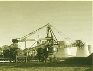
Coal stockyard handling plant
Coal from Khutala mine is crushed in three 1 200 t/h capacity crushers and then transported on overland conveyor belts to the coal stockyard. The stockyard coal handling system comprises two conveyor streams, each rated at 3 600 t/h, and two stacker re-claimers with stacking and re-claiming rates of 3 800 t/h and 2 800 t/h respectively. The system is designed to direct the coal in one of three ways.
1. Onto the stockpile via the stacker re claimer
2. Directly to the power station (by-pass mode)
3. To both stockpile and power station simultaneously
The stacker re claimer operates accordingly and can feed the station with coal re- claimed only from the stockpile. Other plant located on the coal stockyard is:
• A storage silo positioned between the mine and the coal stockyard with a storage capacity of 2 000 t:
• A calibration bin to calibrate the mass meter situated on the conveyor belt, which monitors the mass of coal fed to the station for payment and control purposes.
• An auto sampling plant adjacent to a surge-bin which checks the quality of the coal delivered by the mine.
• A storage silo positioned between the coal stockyard and station with a storage capacity of 2 000 t.
Two 2 660 t/h capacity belts carry the coal from the stock-yard storage silo to three 1 000 t transfer bins. Each of the transfer bins feeds 1 050 t/h capacity dual incline belts, which lead into the boiler house at 57 m level. The coal is then deposited into five 1 000 t capacity mil bunkers through a system of conveyor belts.
Ash handling
At full load, each boiler produces up to 540 t of coarse ash and 2 450 t of dry fly ash per day at 32% ash content. Coarse ash is removed continuously from the hoppers at the bottom of each boiler by a submerged scraper conveyor of the drag link type. Fly ash is removed from the precipitator hoppers by chain conveyors and discharged into a concrete storage bunker which serves two boilers. From there the ash is fed into conditioners where it is moistened with 10-15% water before being fed onto the transverse ash conveyors which transport the mixture of coarse and fly ash overland to the ash dump site approximately 1.5 km away. Here stackers and spreaders place the ash in layers which are subsequently covered with topsoil and regressed.
Low pressure services
The low-pressure services building contains the compressors for control and service air and the pumps supplying demineralised water to the boilers, as well as the potable water and fire pumps. Recovered water from the clean and dirty dams is used for ash conditioning, ash cooling the belt washing. Raw water is gravity-fed from a 410 000 m³ reservoir to the water treatment plant. The auxiliary cooling system, which consists of an open and closed circuit, provides cooling water to all auxiliary turbine and boiler equipment.
Storm-water collection and return system
Separate underground pipelines convey storm and dirty water to separate dams south of the station. The dirty water dam has a capacity of 200 000 m³ and the clean water dam a capacity of 80 000 m³. the station is designated as a zero discharge power station, which means that al dirty water from the station is captured and re-used. Low flows (900 litres) of dirty water pass through screens, plate separators, an ash settling plant and oil skimmers to remove most of the ash, oil and grit. Two berms at the dirty dam ensure the trapping of any ash which might have bypassed or been carried over from the ash removal plant. In the event of very high rainfall, the dirty dam overflows into an emergency dirty water dam which has a capacity of 40 000 m³ and then into the clean dam, thus diluting any effluent before spilling into the natural watercourse. The dirty water pump station may draw water from any of the three dams and pump it back to the power station. This water is used either for bottom ash quenching after which it circulates back to the dirty dam through the screening system, or for ash conditioning.
Water treatment plant
The water treatment plant has two process streams for the production of potable and demineralised water. Raw water is supplied via the Khutala pump station at Matla power station, from the Usutu River. Vaal river water can be pumped in cases of emergency.
Potable water production
The potable water plant consists of clarification and filtration units. The clarifiers are of the plate-type pulsator design and require a minimum amount of maintenance. These units clarify the raw water, removing turbidity, suspended matter and colour, using primary coagulants and flocculating acids. Precipitated matter is drawn off the units as sludge. The filtration plant comprises rapid gravity filters, using sand as a filtration medium. The filtered water is produced in accordance with SABS Standard 241. The final pH of the water is adjusted using soda ash. This plant can produce up to 19 200 m³ of potable water per day, which is stored in an elevated storage tank with a capacity of 2 500 m³
Demineralised water production
Only recovered water is used in this plant. It is fed into an ion exchange plant which producers the fully demineralised water for boiler feed. The ion exchange plant consists of three separate trains of ion exchange units, each of which can treat and produce 200 m³ of water every hour. The demineralised water is then pumped to the station or into any of the three circular demineralised water storage tanks, which a combined capacity of 10 000 m³. All waste effluents from the clarification, filtration and ion exchange plants are recovered within the respective plants and neutralised. After treatment, the waste water is utilised for ash conditioning or for bottom-ash quenching.
Civil engineering features
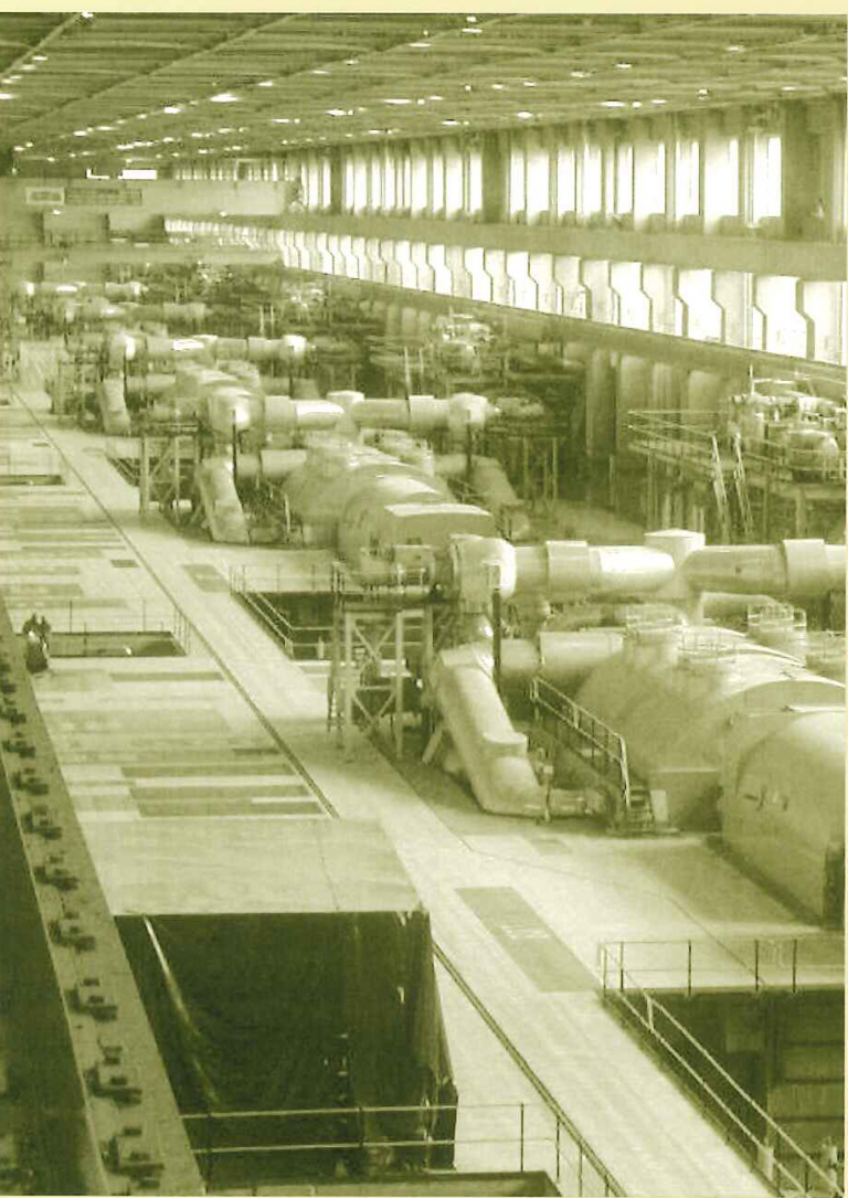
Turbine hall structure
The turbine hall is 526 m long, 33 m wide and 33 m high at roof level. It is constructed of reinforced concrete with structural steel roof trusses and galvanised roof sheeting. Two electrically operated 1 00 t capacity overhead travelling cranes span the turbine hall at the 27 m level. The structure rests on foundations at varying depths, using mass concrete fill to the underside of pad foundations. The founding stratum is constituted of three different, highly variable igneous rock formations (felsite, granite and diabase) that range from depths of 2 m to 13 m below terrace level. In the design of the concrete superstructure the following factors were taken into account.
•Dead load
•Live loads
•Wind loads
•Crane loads
•Secondary effects of creep of the concrete under sustained load
•Shrinkage of the concrete immediately after construction
•30º C differential temperatures across the structure
•The effect of up to 5 mm differential settlement of the column foundations
No seismic loadings were considered in the design as the power station is not located in a seismically active zone.
Chimneys
The two chimneys are 275 m, high structure, each having three internal brick flues, and their foundations rest on weathered bush-veld granite. The base of each concrete windshield is approximately 22 m in diameter. The chimney ring foundation is at a depth of 2.8 m below terrace level and has an internal diameter of 18.3 m and an external diameter of 125.76 m. Other details are as follows:
Dear load of chimney280.2 MN
Normal wind load (resultant forces)5.72 MN at 171 m
Bearing pressureDL only – 1.19 MPa
Normal wind – 1.90 and 0.31 MPa
Extreme wind – 2.48 and 0.27 MPa
Predicted settlement of the chimneys under dead loads is approximately 10 mm and differential settlements under dead load are expected to be about half the average settlement.
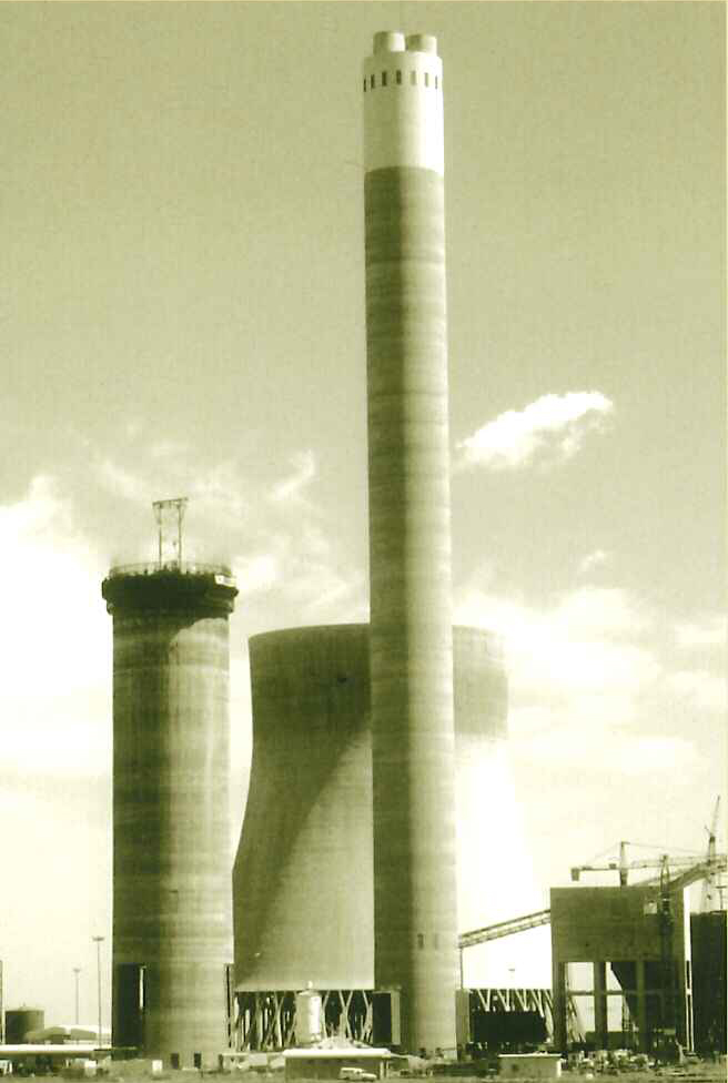
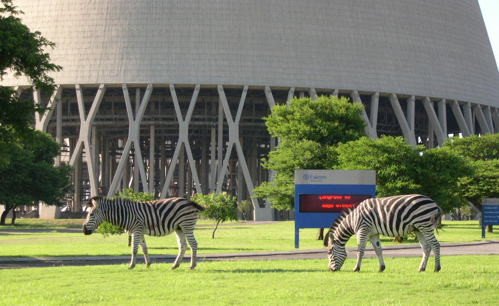
Cooling towers
With a height of 165 m and a base diameter of 165 m each, the cooling towers are the largest in the world. Each shell required 16 800 m³ of concrete and 1 170 t of reinforced steel to construct. The shell thickness varies from 1.5 m at the base to a minimum of 250 mm. In order to support this structure, 52 X-shaped cross columns per tower were used instead of the normal V-shaped columns. These 25 m high columns stand on a series of piles with a ring beam on top. Each one has a mass of 133 t, required 53.3 m³ of concrete and 16.5 t of reinforcing steel to construct and utilises 210 m² of shuttering. They were cast in situ and pond floor level several weeks before being lifted into position. The lifting method, using steel lifting legs and winches, is unique in South Africa and was specially designed for this application. The crucial angle at which the column was finally positioned was obtained by using a 200 t jack under the prop to make final adjustments.
| |||
Technical Data |
|
| |
Generating capacity Installed capacity | 6 x 686 MW units 4 116 MW |
| |
Boilers |
|
| |
Number of boilers | 6 |
| |
Boiler design pressure | 19.28 MPa (abs) |
| |
Coal consumption per boiler at MCR | 97.1 kg/s |
| |
Total air heater surface area per boiler | 126 200 m² |
| |
Total furnace heating surface per boiler | 4 076 m² |
| |
Superheated steam pressure | 17.24 MPa (abs) |
| |
Superheated steam temperature | 540ºC |
| |
Reheated steam inlet pressure | 4.06 MPa |
| |
Reheated steam inlet temperature | 312.8ºC |
| |
Total water content drum and furnace wall (cold) per boiler | 240 t |
| |
Maximum evaporation per boiler | 577 kg/s |
| |
Re heater flow per boiler | 522 kg/s |
| |
Overall boiler efficiency | 92.35% |
| |
Economiser inlet water temperature | 247ºC |
| |
Coal Mills |
|
| |
Number of tube mills per boiler | 5 |
| |
Burners |
|
| |
Number of pulverised-fuel burners | 40 |
| |
Number of oil burners per boiler | 20 |
| |
Maximum consumption of fuel oil per oil burner | 1 161 kg/h |
| |
Turbo-generators |
|
| |
Number of turbo-generators | 6 |
| |
Live-steam flow (100% MCR) | 560 kg/s |
| |
Heat rate at average annual back pressure of 13.6 kPa (100% MCR) | 8 478 kj/kWh |
| |
Superheated steam pressure | 16.1 MPa (abs) |
| |
Superheated steam temperature HP inlet | 535ºC |
| |
Steam pressure in HP outlet | 4.1 MPa (abs) |
| |
Steam temperature HP outlet | 331ºC |
| |
Re heated steam pressure IP inlet | 3.69 MPa (abs) |
| |
Re heated steam temperature IP inlet | 535ºC |
| |
LP turbine exhaust area | 4 m x 2.96 m |
| |
Total mass of each turbo generator set (excluding condenser) | 878 t |
| |
Efficiency of turbine at nominal load | 42% |
| |
Turbine peak rating | 733 MW |
| |
Generator output (100% MCR) | 686 MW |
| |
Generator output (maximum) | 729 MW |
| |
Generator maximum rating | 810 MVA |
| |
Generated voltage | 22 kV at 50 Hz |
| |
Mass of generator stator and rotor | 373 t |
| |
Mass of exciter set | 30 t |
| |
Efficiency of generator | 98.8% |
| |
|
|
| |
Feed pumps |
| ||
Number of feed pumps per unit | 3 (2 in service, 1 standby) | ||
Type | Variable speed, electric motor driven | ||
Electric variable-speed motor at MCR | 7.708 MW | ||
Feed pump flow at duty point at MCR | 280 kg/s | ||
Feed pump pressure at duty point at MCR | 21.1 Mpa (abs) | ||
Chimneys |
| ||
Number of chimneys | 2 | ||
Type | Three-flue with concrete windshield | ||
Height | 275 m | ||
Internal diameter of windshield | 20.80 m | ||
Internal diameter of flue | 7.75 m | ||
Cooling Towers |
| ||
Number of towers | 6 | ||
Height above ground level | 165 m | ||
Base diameter | 165 m | ||
Throat diameter | 101.7 m | ||
Diameter at top | 104.2 m | ||
Minimum shell thickness | 250 mm | ||
Re-cooled water temperature at design point | 33.7ºC | ||
Water inlet temperature at design point | 48ºC | ||
Cooling elements |
| ||
Tube material | Galvanised steel | ||
Total length of tubing | 1 980 km/tower | ||
Number of cooling sectors per tower | 11 | ||
Number of cooler bundles per sector | 32-58 | ||
Cooling water pumps/units |
| ||
Number duty units 1-3 | 3 at 50% | ||
Number duty units 4-6 | 2 at 50% | ||
Pump discharge head | 19.5 m | ||
Flow rate at design point | 15.4 m³/s | ||
Power consumption at design point | 3.41 MW | ||
Cooling water ducts |
| ||
Internal diameter | 3.1 m | ||
Wall thickness | 16 mm | ||
Material | Mild steel B54360GR43A | ||
Condensers |
| ||
Number of condensers | 2 per unit | ||
Condensers cooling surface | 2 x 20 383 m³ | ||
Steam pressure inside condenser at 100% MCR depending on ambient air temperature | 13.6 kPa (abs) | ||
Number of tubes | 2 x 23 976 | ||
Diameter of tubes and wall thickness | 22 m; 0.7 mm | ||
Length of tubes | 12.38 m | ||
Number of passes of circulating water | 2 | ||
Major contractors |
| ||
Boilers | ABB | ||
Turbo-generators | Siemens | ||
Main civil works | Gills-Mason Construction Co (Pty)Ltd | ||
Chimneys | Karrena Africa (Pty) Ltd | ||
Generator transformers | ABB | ||
Cabling (permanent) | Kilpatrick (Pty) Ltd | ||
Terrace earthworks | Gillis-Mason Construction Co (Pty) Ltd | ||
Main instrumentation | ABB | ||
Coal handling stockyard | PHB Wesserhȕtte (SA) (Pty) Ltd | ||
Coal-handling terrace | Fives Cail Titaco (Pty) Ltd | ||
Water treatment plant | Aquazur Reunert (Pty) Ltd | ||
Indirect dry-cooling | DB Thermal (Pty) Ltd | ||
Station services building | LTA Civil Engineering (North) Ltd | ||
Boiler feed pumps | Siemens | ||
Low-pressure services | Titaco Contracting (Pty) Ltd | ||
Raw water reservoir | Gillis-Mason Construction Co (Pty) Ltd | ||
Coal stockyard civil works | Gillis-Mason Construction Co (Pty) Ltd | ||
| |||