Lethabo Power Station
Introduction
The Tswana word “Lethabo” was aptly chosen as the power station’s name: it means “good living, happiness” and reflects the substantial contribution Eskom is making to enable South Africa to reach for high standards in industrial, commercial and social life. The advanced power generation technology applied at Lethabo reinforces Eskom’s reputation as a world leader in this field.
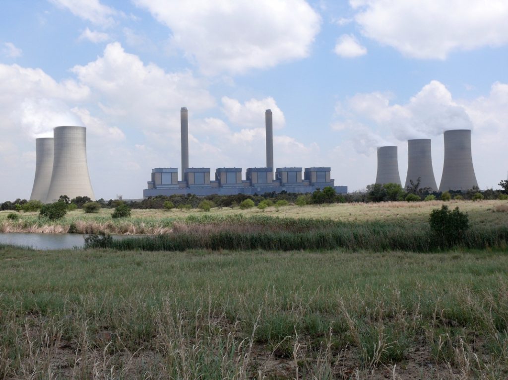
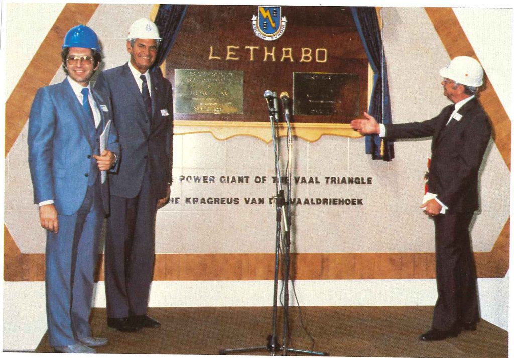
Situated in the northern Free State at an altitude of 1 460 m, Lethabo lies approximately 10 km south of Vereeniging and 25 km east of Sasolburg. Lethabo comprises 6 X 618 MW generating sets. (Production units). Unit 1 went into commercial operation in December 1985 and the last of the six production units was commissioned in December 1990.
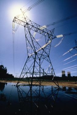
Its proximity to the heart of the Vaal Triangle enables Lethabo Power Station to feed energy into Eskom’s 275 kV transmission network for distribution to its customers
Notable features of the civil works
Site clearing and terracing
Extensive environmental studies were conducted at the chosen site, in accordance with Eskom’s established policy of protecting fauna and flora considered valuable to the country’s heritage. The land and vegetation in question were in a deteriorated condition and it was established that the rehabilitation programmes implemented as part of Eskom’s normal operations would contribute considerably to the restoration and revaluation of the whole area.
Site clearing, which began in 1980, necessitated the removal of 350 ha of bluegum plantation. It is estimated that 190 000 trees were cleared within five months. During excavation work, 2,2 million cubic metres of earth was levelled for the successive terracing stages and a 400 mm deep layer of ash and sand mix was used to provide the final surface.
Piling and foundations
Lethabo is situated in one of the areas of heaving soils prevalent in the Free State. The particular expansive characteristics of the soils underlying the site necessitated in-depth studies for the formulation and optimisation of the foundation designs.
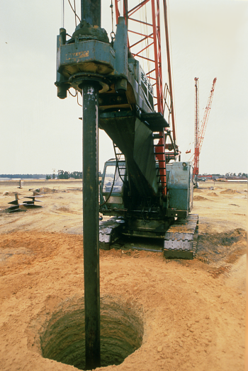
The findings, which were presented in a series of papers at South African and international geotechnical conferences, led to the development of sophisticated methods of piling which were implemented for all major structures on the site.
Piles were installed in competent soil layers at depths of more than 25 m, and the top 15 m of each pile was isolated from the upper layers of heaving clays. All the piles were provided with a bitumen-based slip coat. The piling contract at Lethabo was the largest contract of its kind in South Africa. Foundations were constructed on these piles with a 750 mm layer of sand under the foundation. When curing of the foundation was complete, this layer of sand was excavated by hand to leave a void under all the pile foundations. This void isolates the foundation from the expansion and contraction of the underlying soils. All major structures and floor slabs were constructed in a similar manner.
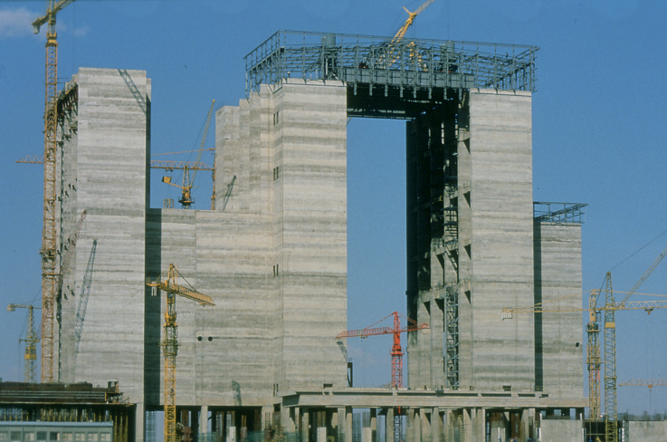
Boiler house structure
A special feature of the boiler house structure at Lethabo is its 82,6 m high concrete superstructure with its sliding-shutter building technique. This type of structure, already employed at Matla Power Station, compares very favourably in technical as well as cost terms with the more conventional steelwork structure. This structure incorporates the coalbunkers with their stainless steel inner lining.
Boiler house under construction
The boiler itself hangs from steel girders supported on top of the concrete structure of the boiler house. The floor at the 16 m level is constructed in the form of a concrete slab. All other floors and galleries are constructed of steel beams and open grid flooring fixed to the concrete walls.
Turbine house structure
The steel turbine house structure contains the six turbo-generator foundations and supports, each consisting of 8 000 m³ or 20 000 tons of reinforced concrete. The turbine-generator “island” is a separate foundation compared to the rest of the station. The reason for this is to isolate the turbine-generator, preventing external vibrations affecting the alignment, balancing and operation of the plant.
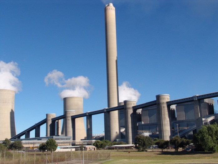
Chimneys
Lethabo has two chimneys, each 275 m high, to enable the flue gases to be emitted through the normal inversion layer of the atmosphere and to be dispersed over vast distances. Each chimney comprises a reinforced concrete windshield, with an external diameter of 20,5 m, enclosing three flues. Each flue, made of interlocking refractory bricks, serves one boiler. The internal diameter of each flue is 6,9 m, allowing a gas flow of 1 150 m³/s. The diameter of the foundation slab is 30,6 m and it is supported on 45 augered piles of 1,5 m diameter. The chimneys, like all the major structures at Lethabo, were constructed with a void beneath the foundations to allow for a heave of the underlying ground. All the piles were provided with a bitumen-based slip coat.
Approximately 11 500 m³ of concrete and 17 000 m³ of brickwork were used in the construction of each chimney. In addition to a staircase, a service lift was installed inside the windshield for inspection and maintenance.
Lethabo: the basic cycle
Introduction
In South Africa, most of our electricity comes from thermal power stations fuelled by coal. Most of these coal-fired stations comprise six production units. Each production unit has a boiler, a turbine coupled to a generator-rotor, control and auxiliary support systems.
The following describes how a 618 MW boiler/turbine generating unit, such as at Lethabo Power Station, produces electricity. Although different technologies and designs are used elsewhere in Eskom, the basic principles remain the same.
A Converter of energy
A power station is a converter of energy. The combustion of fuel, a chemical energy conversion process, generates heat to convert water into steam at a very high temperature and pressure. The heat energy contained in the steam acts as the driving force for the huge turbines, converting heat energy into rotating mechanical energy. Coupled to the turbine shaft is a generator where electrical energy (electricity) is produced.
The production process
The boiler
Boilers, 27 storeys in height, (74m) are housed in the rectangular blocks (structures) that give power stations their distinctive look. The structures themselves are as high as 35-storey office buildings (84 m).
The boilers at Lethabo Power Station are of the radiant water-tube type, operating on a natural circulation principle. They consist essentially of a large tubular-walled furnace, a steam drum, an economiser, three superheaters and two re-heaters. The boiler generates 509,7kg/s of steam at a pressure of 17,32 MPa and 540 °C, at a maximum continuous rate (MCR) to produce 618 MW of power.
The boilers have been designed to use the energy released by the burning coal to heat water as efficiently as possible. Not all the heat energy released through the combustion process is required to heat (boil) the water in the boiler tubes. To make the most efficient use of the heat energy produced, the exhaust flue gases are used to preheat the water entering the boiler. More about boiler operation under the headings water and steam.
Coal supply
The New Vaal Colliery, which supplies Lethabo with coal, has direct connections with South Africa’s earliestmining ventures. The coalfield in which the New Vaal Colliery lease area lies was disxovered by GW Stow in 1878. In 1880 Stow and Sammy Marks formed the Zuid Afrikaansche en Oranje Vrystaatsche Kolen- en Mineralen-Myn Vereeniging, and it was from this company that the town of Vereeniging derived its name. Coal was mined for the requirements of the diamond fields, the Witwatersrand gold fields and the railways.
The colliery was producing 720 tons of coal per annum by 1884. In 1892 an attempt was made to open a mine in the present Valley area, which lies directly to the south of the Maccauvlei East area where mining operations for the New Vaal Colliery now take place. The first sod was turned by President Reitz, who named the mine Cornelia, after his mother. A more successful attempt was made in the Maccauvlei West block in 1894 and was known as Cornelia 2.
This mine worked the reserves of coal in both the Maccauvlei East and West blocks until 1930. These operations succeeded in removing only some 6-7% of the coal reserves of the Maccauvlei East block.
The New Vaal Colliery is now mining the same reserves. The modern opencast techniques used will guarantee a yield of some 600 million tons of coal, sufficient to supply Lethabo Power Station for ±40 years.
Three coal seams worked simultaneously, using unique techniques to deal with the earlier underground mine workings. Output at full production is ±15 million tons per year mined from three pits. The mine is unusual in having a dense-media coal-washing plant operating at a relative density of between 1,8 and 2,0 and designed primarily to remove contamination caused by collapses in the old workings.
The coal is of unusually low quality, having an average calorific value of about 16 MJ/kg with up to 42% ash. Lethabo Power Station therefore represents a major step in the utilisation of low-quality coal in South Africa as well as internationally. Experience gained at Lethabo will eventually have an enormous impact on the exploitation of South Africa’s indigenous energy resources, both for use in SA as well as internationally.
How coal gets to Lethabo
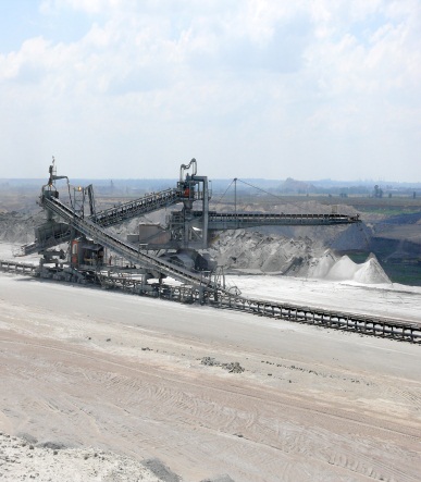
Lethabo Power Station burns ±50 000 tons of coal every day, enough to fill 50 000 1-ton LDV’s (bakkie) loads of coal per day. Belt conveyor systems are used to transport the coal from the mine to a coal stockyard and then to the power station site. The purpose of the coal stockyard is to ensure that there is sufficient coal reserves available to keep the power station in operation should the mine experiences production problems of whatever kind. Total storage capacity of the stockyard is 3,82 million tons and coal can be transferred to the power station at a rate of up to 3 000 tons per hour.
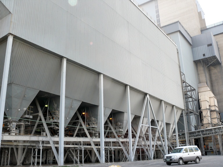
At the power station, coal is stored in six 6 x 5 500-ton capacity silos. Each can serve two boilers if necessary. From the silos, belt conveyors transfer the coal to 800-ton coalbunkers, of which there are six per boiler, giving an effective storage capacity of 12 hours operation at full load.
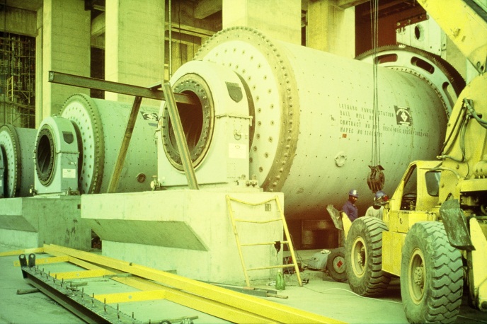
Pulverisers (mills) and combustion
Coal from the bunkers is fed into the mills through volumetric variable speed belt feeders. The coal is pulverised to a fine powder in giant grinding mills – pulverised fuel (PF). The output of the mills is determined by the load requirements of the boiler. Inside the rotating tube mills, steel balls (grinding elements) pulverise the coal. There are ±96 tons of balls (±10 000) in one mill. As mill balls wear away during pulverisation, ±1 ton of balls are added to each mill almost every 100 operating hours. There are six mills per boiler, 5 of which are in service for full-load production. Thus, one mill is always on standby providing a spare capacity when required and or for maintenance requirements.
Why crush the coal? This is because PF burns quickly, like gas. The coal “dust” particles are 70 microns and smaller! At full capacity, each boiler requires between 350 and 400 tons of coal per hour, depending on the calorific value of the coal.
The mixture of powdered coal is blown into the furnace by a blast of hot air supplied by two primary air fans, one fan for three mills. A total of 36 burners are arranged in three banks of six each, on both the front and rear walls of the furnace. The furnace area is 12672m3.
Burning coal in this huge furnace is like creating a huge fireball with a temperature of 1 200ºC at full load. During a light- up, fuel oil is used. The fuel oil is stored in two storage tanks with a combined capacity of 1,2 Ml. Each coal burner incorporates an oil burner. Fuel oil is atomised as it is injected thorough the oil burner, at a pressure of ±4,5 MPa, into the furnace.. The atomised oil is ignited with a propane gas ignition system. The fuel oil system comprises one low-pressure (LP) and one high-pressure (HP) pump working in series to supply oil to the boiler. Each oil burner has its own control system and can be selected for a high or low-firing mode, with capacity of 760 kg/h and 650 kg/h respectively.
Two huge forced – draught fans (FD) supply atmospheric air (oxygen), as combustion air to the boiler. Exhaust gases from the boiler leaving the economiser, at a temperature of ±350°C, are used to heat the air in two rotary-regenerative air heaters to approximately 250ºC. Tubular primary air heaters are also used to heat the air for the removal of the PF from the mills.
Two induced draught fans (ID) extract the flue gases from the boiler exhaust gas pass areas. The gases are then emitted into the atmosphere via electrostatic precipitators and two 275 m tall smokestacks.
Ash collection and disposal
The coal has an ash content ranging between 34% and 42%. The burn rate of ±16 million tons of coal a year therefore produces very large quantities of ash. The station burns approximately 50 000 tons of coal per day, producing almost 23 000 tons of ash every day. Almost 90% of the ash produced in the combustion process is called fly ash or pulverised fuel ash. The reason for this is that the coal is pulverised into a very fine dust, rather like cake flour, before being fed into the boilers. Larger particles of ash, called coarse ash or boiler bottom ash, drop down from the furnace and collected at the bottom in the ash hoppers of the boiler.
The fly ash from the flue gas stream (exhaust gases from the boiler) is extracted by means of electrostatic precipitators. The precipitators installed at Lethabo are the largest at any Eskom power station. There are four precipitator casings per boiler with seven electrically charged plates and wires per casing. The fly ash is dislodged from the fields by means of a rapping system and drops into collecting hoppers from where it is transferred by a chain conveyors system and bucket elevators into concrete ash bunkers. To eliminate dust being released during transporting of the fly ash, the ash is drawn from the bunkers and mixed with ±17% effluent water. This dampened ash is transported to the ash disposal site via an open overland conveyor system. There are two streams of conveyors, one always in operation.
The coarse ash (bottom ash) is transferred to the main ash conveyor system via a submerged scraper conveyor and a pipe conveyor system. The latter was installed due to the limited space available in the basement area of the boiler. The Japanese pipe conveyors at Lethabo are among the first pipe conveyors ever installed in South Africa.
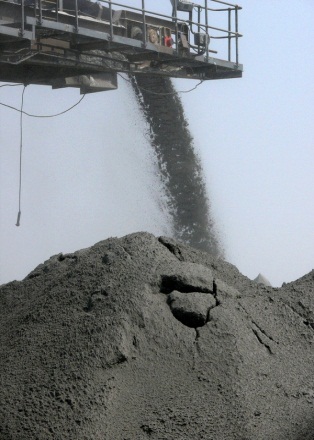
The ash (coarse and fly ash) is still in a semi-dry state suitable for dumping in the opencast workings of the mined area which has been backfilled with soil. For ash dumping, two stackers, each served by a shiftable and an extendable conveyor are used. Dumping is done at intervals onto two dumps. The height of a dump is 50 m. Mobile plant is employed for final levelling and shaping of the dump. Eskom’s policy of land restoration and rehabilitation is applied here, as at all other power stations. The ash dump is landscaped to minimise visual pollution.
Water circulation
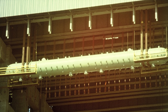
Very pure demineralised water enters the boiler through an array of pipes called the economiser, placed in the second (rear) gas pass of the boiler. The water is pre-heated by the hot flue gases leaving the boiler. Before entering the boiler steam generation tubes, the water flows into the steam drum, which acts as a steam/ water reservoir. In the drum, saturated steam (wet steam) is separated from the water by cyclone separators and scrubbers. The boiler steam drum, which has a length of 25m, a diameter of 2 m, a wall thickness of 156 mm and a mass of 285 tons, is located at a height of 77 m, outside of the heat source of the boiler. The operating pressure inside the drum is 18 MPa
Topsoiling and revegetation are conducted on an ongoing basis so that eventually the whole area will be rehabilitated and restored for agricultural use, mainly grazing. An irrigation system has been employed for dust suppression on the exposed working areas of the dump. When the dumping area is full in ±40 years’ time it will cover an area of approximately 500 ha.
Due to the low sulphur content of Lethabo coal, 0,6%) a sulphur-trioxide injection system (SO3) has been installed to enhance the operation of the precipitators, improve the resistivity of the ash onto the electrically charged fields. Bag filters and flue gas conditioning systems are in use at some Eskom power stations.
From the steam drum, water flows to the bottom of the boiler through seven large bore pipes, downcomers, on the outside of the boiler. These downcomers are connected to tubes, the steam generation tubes, through distribution headers. These tubes form the four walls of the boiler front gas pass. These boilers are also known as water-cooled furnaces. The furnace tubes (walls) eventually re-join the drum.
Steam flow
To use up yet more of the heat generated during the combustion process, steam from the top of the drum flows to banks of tubes, superheaters, situated in the gas pass area of the boiler. Here the hot flue gas is used to superheat the steam to a temperature well above the boiling point of water. There are three stages of superheating: primary, platen (second stage) and final superheaters. The primary stage is situated in the rear gas pass and the platen (of pendant design) in the first gas pass. The platen superheater is positioned very close to the top of the combustion area of the boiler. This means it is exposed to very high flame temperatures, ±900°C. The final superheater stage is placed in the crossover (nose) between the first and second stage gas passes.
Steam temperature control is done through attemporators situated between the platen and final stage superheaters. Water from the feedwater supply pumps is used for temperature control. The steam, called live steam, leaves the boiler and flows to the HP turbine at a temperature of 535 ºC.
The boilers are of the reheat design. On returning from the HP turbine, the steam flows through primary and secondary reheaters, where steam is reheated to 535 ºC. It then flows to the IP and LP turbines to complete the cycle. The first stage of the reheaters is placed in the second gas pass (rear) area with the second stage, final re-heater, in the crossover between the first and second gas pass. Temperature control is similar to the superheater control system. i.e. water injected into the steam between first and second stage reheaters.
For boiler start-up operation and in the event of a large load rejection on the turbine, the HP turbine bypass system is provided to keep the boiler in operation while the turbine is not running.. This system allows steam from the boiler final superheater outlet to pass, via a pressure reducing valve, to the HP exhaust pipes (cold reheat) leaving the HP turbine. This bypasses the HP-stage turbine and allows the boiler to be operated independently via the HP/LP bypass. This means that the boiler can stay in operation, ±33% of MCR at reduced output, and total steam flow by-passing the turbine, completing the steam flow cycle. Before the steam enters the condenser, a large quantity of water is injected into the steam prior entering the condenser. This is to ensure the steam temperature does not exceed normal condenser operating temperature of 35°C.
Steam admission to the HP an IP turbines flows through hydraulically operated emergency stop valves, ESV’s. The control of the steam flow during start-up is via four hydraulically operated control valves. When the turbine is on load, speed control is only through the HP control valves and via an electro-hydraulic speed control system.
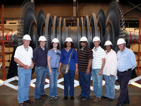
The turbine – impulse- reaction type
Each of the six turbo sets has a high-pressure turbine (HP), an intermediate pressure turbine (IP) and two double-flow low-pressure turbines (LP), all arranged in tandem configuration. The turbine rotor operates at a rotational speed of 3 000 r/min that represents 50 Hertz on the Eskom national grid frequency.
The HP and IP cylinders have an inner and outer casing. This design reduces the impact of the high live steam pressure, primarily at the HP turbine, and also increase the thermal flexibility of all turbine casings (thinner wall thickness), allowing for fast start-ups and rapid load variations.
The HP and IP turbines comprise 10 stages each, while the LP turbines, double flow design, consist of six stages per flow (4), totalling 26 stages.
Each turbine rotor stage uses a specific amount of thermal energy form the steam required to turn the turbine and generator rotor shafts. Towards the final stages, they require about 16 500 times more volume than at the HP inlet. Each of the turbine stages contributes to the total 618MW output of the generator.
– The HP turbine delivers 154,5 MW (25%),
– IP turbine 278,1 MW (45%)
– Two LP turbines 92,7 MW (15% each) at design point.
The turbine and generator efficiency tests revealed that 635 MW continuous operation is allowable at high load demands.
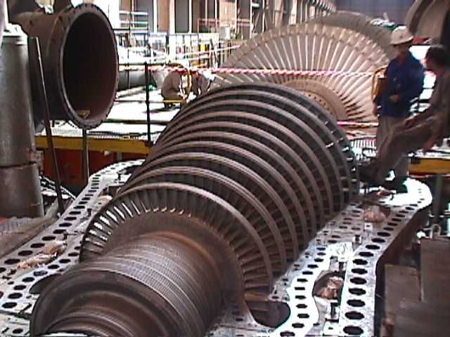
The turbines contain two sets of blades. One set is fixed to the turbine inner casing by diaphragms that direct the flow of steam via their guide vanes. The other set is fixed to the rotor disks that turn the rotor by transforming the energy impact from the fast moving steam. The design of these moving blades is critically important and engineered to optimal shapes in order to abstract the maximum energy from the steam. The design of a turbine is based on the curvature of the blades which is a combination of mainly impulse and, to a lesser degree, reaction design. This design produces a lower resultant thrust on the rotors than a mainly reaction design.
A thrust bearing is employed between the HP and IP cylinders to absorb residual thrust from the rotors. A major portion of the actual thrust in the turbine is balanced using steam and dummy piston technique.
All the turbine and generator rotors are supported by two journal bearings per rotor. Forced oil lubrication is employed that also serves as cooling media at the rotor journals.
Steam flow
Live steam, superheated steam at 492 kg/s at a temperature of 535 °C and a pressure of 16,1 MPa is admitted into the HP turbine via the four HP steam emergency stop and control valves. Spent steam from the HP turbines is returns to the boiler via the cold reheat piping system at about 332 °C and pressure of 4.1 MPa to the re-heaters. Again, making use of the hot gases in the boiler, the temperature is raised to 535 °C at a pressure of about 3,67 MPa. It then enters the IP turbine and expands via ten stages to a temperature of 204 °C at a pressure of 0,29 – 0,3 MPa.
From the IP turbine exhaust, the steam is carried into the LP cylinders via large crossover pipes, one of which leads to each LP cylinder located on either side of the centre of the shaft. On entering each LP cylinder, the flow of steam splits equally and expands in two directions through the six stages of each flow. The steam becomes sub-atmospheric at about the penultimate stage and the last stage handles wet steam with a moisture content of roughly 8-9%. The last-stage blade, which has an effective 950 mm foil length, represents one of the largest blades for a machine of this speed, with a tip velocity of 550 m/s at nominal speed (3 000 rpm). The steam travels through the turbines with an axial velocity of 240 m/s and is expelled through a bell mouth exhaust leading to the condenser neck. (See section on condensation)
Feed-heating plant
As the steam moves through the turbine, some steam is bled off (extraction steam) to preheat feedwater and thus reduce the amount of coal needed to boil the water and produce steam. There are four stages of low pressure feedwater heaters and two stages of high pressure feedwater heaters where the water reaches a temperature of approximately 248 °C prior to entering the boiler economiser.
The three low pressure feedwater heaters are of the tube and shell design. The high pressure heat exchangers are of the header type due to their large differential expansions. In both cases, the water flows through the tubes with heating steam around the tubes.
A spray-type de-aerator/feedwater storage tank (heat exchanger 4) is situated between the low and high-pressure heaters. It removes entrained gases in the condensate (feedwater) and heats the water through direct contact with steam extracted from the turbine.
Extraction steam is also used to drive a variable speed turbine connected to a 100% boiler feedwater supply pump. For start-ups and as a back-up, two 60% electrically driven feed pumps are installed. These pumps are of the centrifugal design.
Condensation
As the purified, demineralised water required to produce steam to drive the turbines is expensive, it is used again and again. In order to do this, the spent steam leaving the LP turbines, at pressures between 4 and 7 KPa absolute at a temperature ± 40 ºC, has to be condensed. Huge surface condensers are used in this process.
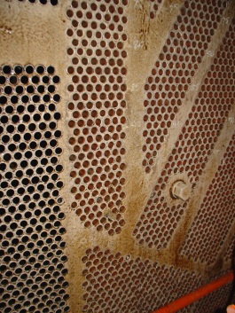
The condensers serving the two LP turbines are of the dual-pressure surface type. The condenser houses the LP-condenser and the HP-condenser, split on the steam side by a wall that reaches into the hotwell. The hot well is the bottom floor where the condensed steam is collected. The vacuum at the steam side of the condensers is established initially by steam-jet air ejectors and maintained under normal operation by water-jet air ejectors. Exhaust steam from the LP cylinders condenses over 32 180 brass and titanium tubes with a collective surface area of 27 900 m². The dual condenser has a heat-exchange capacity of approximately 2 x 400 MW.
Cooling water is supplied to the individual condensers by the cooling water supply pumps (total of six), at a maximum rate of 12,42 m³/sec per unit. The cold water enters the LP condenser in two counter streams via inlet ducts and water boxes that distribute the cooling water uniformly across the tube bundles. The warm water leaves the LP condenser via a water box and enters the HP condenser through crossover ducts and water boxes. The cooling water outlet from the HP condenser returns to the cooling tower via two hot water ducts. The water inlet and outlet water boxes are designed for the equal distribution of the water and are removable should it be necessary to replace or manually clean condenser tubes. The difference in temperature between the spent steam around the tubes and the colder water within the tubes causes the latent heat to be removed and therefore condensation is achieved.
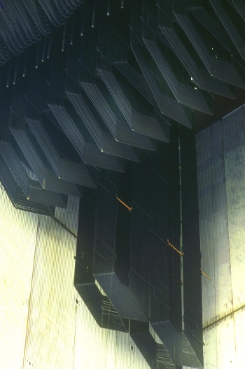
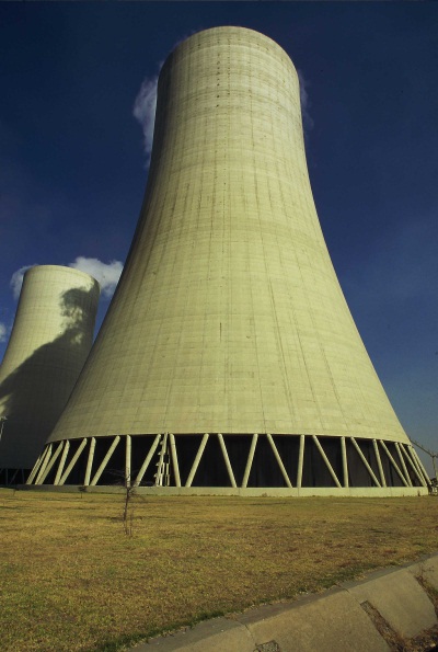
The warm cooling water containing the waste heat goes to the cooling towers. In these amazing “chimneys”, this warm cooling water is sprayed onto layers of plastic grid, breaking the water into fine droplets over a large surface area for sufficient cooling to take place.
The cold water falls by gravity into the pond. Atmospheric air at ambient temperature and due to its density moves up through the tower, from the bottom, and creating an upward draught. The now warmer and lighter air rising to the top of the tower becomes partially saturated with water. This is seen as a plume of water vapour at the top of the cooling tower, evaporating into the atmosphere.
Although heat energy and water is lost inside the cooling towers, this is still the most efficient water cooling method as you have no restriction between cooling water and air. The efficiency of the cooling towers depends entirely on the atmospheric conditions (climate) around the tower. The shape of the cooling tower is largely for structural stability and has no influence on the efficiency.
The six cooling towers have a total thermal load of approximately 18 000 Gj/h. The cooling towers are 164 m in height, with a pond diameter of 112,5 m and minimum shell thickness of 200 mm in the middle.
Cooling water is supplied to the individual condensers by the cooling water supply pumps (total of six), at a maximum rate of 12,42 m³/sec per unit. The cold water enters the LP condenser in two counter streams via inlet ducts and water boxes that distribute the cooling water uniformly across the tube bundles. The warm water leaves the LP condenser via a water box and enters the HP condenser through crossover ducts and water boxes. The cooling water outlet from the HP condenser returns to the cooling tower via two hot water ducts. The water inlet and outlet water boxes are designed for the equal distribution of the water and are removable should it be necessary to replace or manually clean condenser tubes. The difference in temperature between the spent steam around the tubes and the colder water within the tubes causes the latent heat to be removed and therefore condensation is achieved.
The warm cooling water containing the waste heat goes to the cooling towers. In these amazing “chimneys”, this warm cooling water is sprayed onto layers of plastic grid, breaking the water into fine droplets over a large surface area for sufficient cooling to take place.
At some of Eskom’s power stations, direct and indirect dry-cooling systems are in use. Although quite expensive to build, they are designed for water conservation and therefore uses significantly less than the conventional wet cooling system used at Lethabo and other power stations.
The generator
The turbines are solidly coupled to the generator rotor and rotate at 3 000 revolutions per minute. Inside the generator casing are thousands of copper wire coils fixed in a circle, called the stator. The rotor, which is an electromagnet, rotates inside the stator ring. The field current for the rotor is supplied by a main exciter (DC generator) via slip rings.
As the rotor turns, its magnetic poles pass across the stator coils 50 times per second (50 Hz), producing a continuously varying current. The coils are arranged in three groups, producing the current in three sets of windings. This is called 3-phase current and is a way of optimising the rotation of the generator. The result is the alternating current (AC) produced by all power stations.
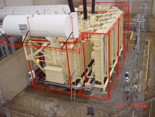
Each generator is rated at 618 MW/687MVA with a power factor of 0,9 (lagging) at full load. The generator produces a current of 13 500 amps, at 20 000 volts, which passes via conductors (bars) and a circuit breaker to the generator transformer. Here the voltage is stepped up to 275 000 volts and the current flow reduced to 1,100 amps.
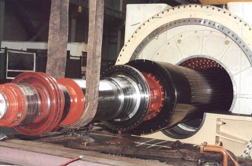
The rotor – an electro magnet
Generator cooling is achieved through two systems. The stator outer windings and rotor windings are cooled by hydrogen at a pressure of 400 kPa and circulated through surface-type water coolers by two axial fans on the rotor shaft.
The circulation of demineralised water through the hollow conductors cools the stator windings internally.
Power from the generator goes via a 20kV air-blast circuit breaker to the main transformer. This is a step-up transformer rated 700MVA, stepping up from 20kV to 275kV. Prior to the main transformer, two step- down transformers step the voltage down from 20kV to 11kV for power consumption for inhouse use. The sent-out rating of a production unit is 593 MW, the difference of about 25 MW being used to run the plant auxiliaries equipment such as feed pumps, mills and fans etc.
From the main transformer, the power is fed onto Eskom’s integrated power grid. All power stations are synchronised to the grid at 50 Hz. The 275 kV switchyard, which is of conventional outdoor construction utilising strung conductors, has a load current capacity of 3 150 A and a short-circuit current level of 50 kA. The electricity is distributed via a high-voltage distribution yard into the integrated network.
Control
Each unit is run as a separate entity with its own controls and instrumentation installed in its own control desks and control rooms. Plant controllers monitor and control the computerised functions associated with start-up, normal operation, shutdown and emergency operation.
The control equipment for an entire unit consists of an integrated system of modulation and binary control, as well as alarm and supervisory functions. The control facilities ensure safe and efficient operation at all times requiring a minimum number of skilled operators.
All operations for normal operation, cold, warm or hot start-ups, loading and de-loading and normal shutdown of the unit are conducted from the control room, either manually, partially automatic or in fully automatic mode.
The modulating control system provides fully automatic load control of the whole process, with facilities for set point control of sub-loops as well as manual control of each drive. Similarly, the binary control provides fully automatic run-up of the major plant groups including the facility of individual drive control. In the event of the failure of running auxiliaries, standby plant is automatically switched on. If main plant groups fail, the unit automatically runs back to the highest possible safe state.
Data logging computers continuously monitor the main operating alarm systems and provide a constant flow of information on video monitors and printouts. All the above operational functions are monitored on a 24-hour basis.
The plant controllers are in permanent contact with Eskom’s national control centre via the station control room. Station control is responsible for operating the in-house electrical reticulation system – outside the jurisdiction of the unit control and outside plant areas such as the the water treatment and coal plants. The national control centre manages and controls the power supply and demand on the integrated power transmission network.
Water supply and treatment
The proximity of the Vaal River has both advantages and disadvantages. It ensures the station of a constant supply from a primary water storage dams, but at the same time requires that stringent measures be adopted to prevent pollution.
The water management system is designed specifically for the treatment, re-cycling and re-use of water. This includes treated sewage, dirty accumulated storm-water and treated (desalinated) mine water. Consequently, the only way in which water can leave the confines of the station is by evaporation, which is mainly from the cooling towers.
Water is pumped from the Vaal River, upstream of a specially constructed weir, to the two on site reservoirs or directly into the different water systems. Sufficient water can be stored in the reservoirs to keep the power station operating at full load for five days. The raw water is fed to the cooling tower ponds and to the raw water clarifiers.
The raw water clarifiers mainly remove suspended matter from the raw water. The water is filtered in pressurised sand filters and then split, either to be chlorinated and pH adjusted as potable water for domestic purposes or demineralised to produce boiler feed water. Sludge from these clarifiers is added to the feed of the concentrated cooling water (CCW) treatment so the water can be recovered.
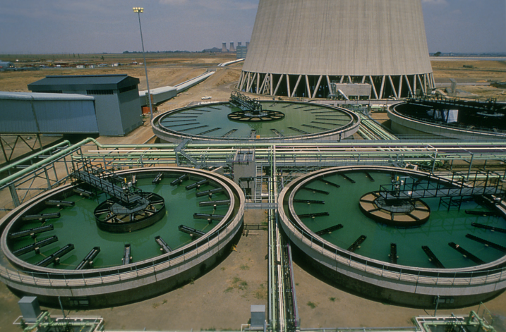
Raw water clarifiers
The automated demineralisation plant uses an ion-exchange process, which consists of three parallel trains. Each train consist of vessels filled with resins. The first vessel comprises a double layer cation unit followed by a de-gas tower, an anion supply pump, a weak base and strong base anion unit and a mixed bed unit containing anion and cation resins.
The demineralised water produced contains residual impurities of a few parts per billion and is stored in three stainless steel tanks, each with a capacity of 2,5 Ml. In addition, each of the six units is provided with a condensate polishing plant which has three mixed-bed units. The resins for the polishers are transferred to the water treatment plant for regeneration and then returned for the next service run.
These units work continuously to ensure the water is in line with chemical requirements for high pressure steam production. They also reduce start-up times and reduce waste of water and heat. The dissolved salts present in the make-up raw water to the cooling towers are concentrated as a result of evaporation.
The daily accumulation of salts and solids in the concentrated cooling water (CCW) must be removed from the system to prevent scale formation and corrosion. This is done by drawing off part of the CCW from the cooling water streams. In a clarifier, CCW is mixed with recovered effluent (station drains, treated sewage and some mine water). The first stage of CCW treatment is the lime softening process which is done in three 45 metre diameter clarifiers. The lime softening process precipitates most of the scale forming species and they are removed from the water by settling to the bottom as heavy particles. The sludge containing a high concentration of solids is removed from the bottom of the clarifier for disposal.
The second stage of CCW treatment is to remove the corrosive species from the water and this is done using reverse osmosis. This plant concentrates all the salts into one small concentrated stream, called the “brine”, and a large clean stream, called the “permeate”. The plant has a 95% salt rejection and 75% water recovery capacity.
All the concentrated effluents, the lime softening sludge, the reverse osmosis brine and the spent ion exchange regenerants, which together contain all the dissolved solids and chemicals introduced into the power station, are mixed together with the ash. The mixture of ash and effluent is conveyed to the ash dump and stacked. The ash solidifies like cement and keeps all the effluents trapped. The ash dump is landscaped, covered with fertile soil and grassed. The effluents are retained permanently in the ash, thus satisfying the concept of zero liquid effluent discharge from the power station.
The design of the water circuit has an inherent flexibility, intended to simplify the operation and management of this highly sophisticated water treatment facility.
|
LETHABO – general specifications
|