Matimba Power Station
Matimba Power Station – The Bushvled Gaint
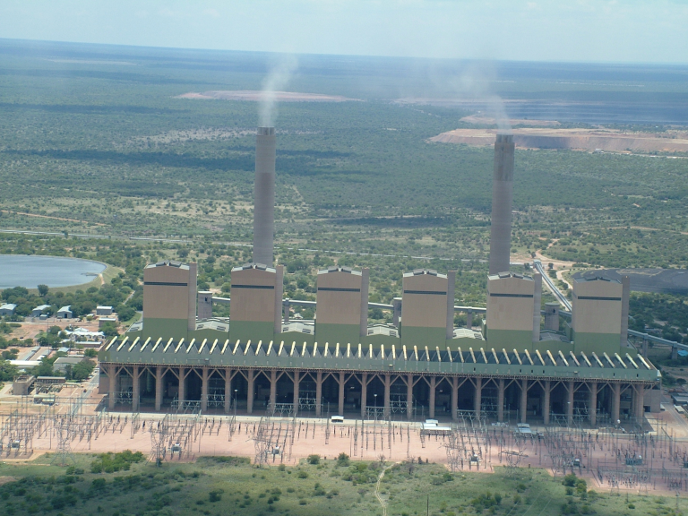
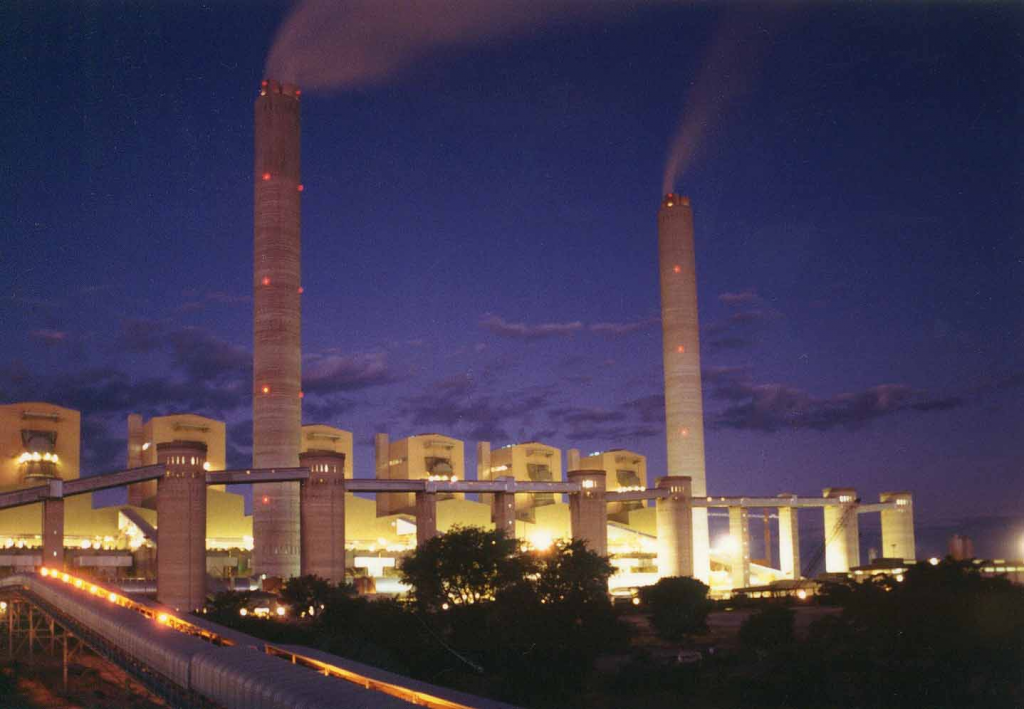
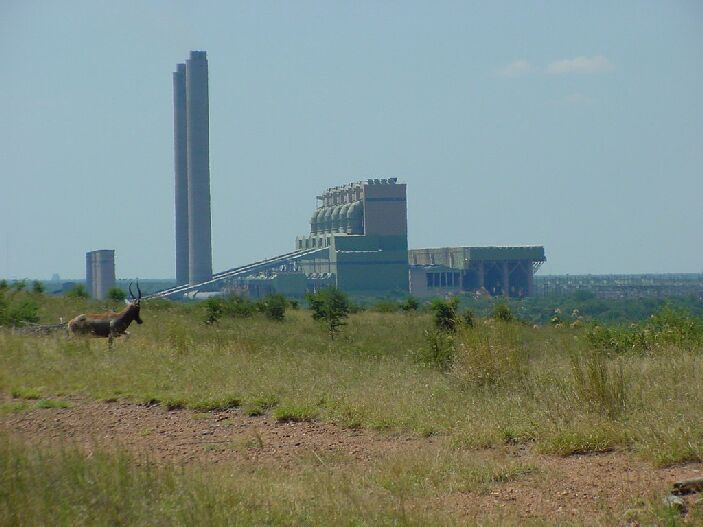
Matimba – the Tsonga word for “power” is an appropriate name for the dry cooled power station near Ellisras in the Northern Western Province. Designed to generate 3 990 MW, Matimba has the world’s largest turbo generators using the direct dry cooled steam condensing system. The adjacent Grootegeluk Colliery has sufficient coal reserves to guarantee Matimba a minimum lifespan of 35 years, extending to a possible 50 years, at 3 580 tons of coal per hour.
OPTIMUM USE OF COAL AND WATER
Constant research has enabled Eskom to reduce its coal consumption to as little as 0,533 KG/KwH sent out. This is especially noteworthy considering the low grade of the coal burned (calorific value between 18 and 22 MJ/kg; ash content ±35%). Not only does Eskom burn coal for which there is no other use, but in so doing it saves millions of tons of better quality coal for export or for specialised industrial use. The Grootegeluk Colliery, which provides ISCOR with high grade metallurgical coal for iron and steel production, is this able to send the waster low grade coal to Eskom. This in effect makes Matimba part of a joint venture which assures maximum beneficiation of the colliery. Ongoing studies to increase the efficiency of water consumption have reduced this figure to 2,02 litres per kWh sent out. (Matimba has already achieved 0,16 litres per kWh and less). The decision to build dry cooling power stations is a further step in the conservation of our country’s limited water supplies.
DRY COOLING VS WET COOLING
Although the expense involved in the construction and operation of a coal fired power station with a dry cooling system is greater than that of one with a wet cooling system, limited available water resources may override economic considerations in determining the choice between the two technologies. Dry cooled systems consume less than 0,2litres/kWh. Compared with the 2,0 litres/kWh required by wet cooled systems. Evaporation losses in wet cooling systems account for approximately 80% of the water requirements of a conventional wet cooled power station. These losses can amount to 1,5 million litres an hour per 600 MW wet cooling tower on the South African Highveld. The choice of dry cooled technology for Matimba was heavily influenced by the severe shortage of water in the area.
DRY COOLING TECHNOLOGY
These are two basic dry cooling systems. The indirect dry cooling system adopts a principle similar to that used in the car radiator, where heat is conducted from the water to the metal of the radiator and from there to the air passing through it. The air remains dry, as it does not come into contact with the hot water. The water is in a closed circuit and evaporation is this minimized. In the direct system steam from the low pressure turbine is channeled directly into the radiator type heat exchanger. The heat is conducted from the steam to the metal of the exchanger. Air passing through the exchanger removes the heat, thus condensing the steam into water to be pumped back to the boiler. Cooling in both the direct and indirect systems can be achieved either by natural draught in cooling towers or by forced draught using fans. Cooling in the Matimba direct dry cooling system, however, is by forced draught, whereas an indirect natural draught system is applied at Kendal power station. The indirect system makes use either of surface condensers as in conventional wet cooled power stations, or of jet condensers. In the former, cold water flows through the tubes of the condenser, removing heat from the steam passing over them. This now heated water flows through heat exchangers arranged inside a natural draught cooling tower. Air to cool the water is drawn through the tower and across the heat exchangers either by natural convection or by electrically driven fans.
In the alternative jet condenser system, exhaust steam leaving the low pressure turbine is condensed by a spray of cold water. The resultant hot water collects in a sump and is pumped through the heat exchangers in the cooling towers as in the surface condenser system. In addition, part of the condensed water is led from the sump of the jet condenser to the boiler. The main advantage disadvantages of this system are the large volume of highly purified water required and the problem of ensuring that no air can leak into the system. The performance of a dry cooling system depends on the ambient dry bulb temperature. Temperatures at Ellisras vary as much as 15 degrees from day to night and in summer will frequently rise to the 40s. Consequently the rate at which the air draws heat from the heat exchangers will vary considerably, as will the back pressure at the turbine exhaust. This will affect the efficiency of the turbines in such a way that the rated 665 MW might only be achieved when ambient air temperatures are low.
PLANNING
The planning of Matimba as a base load station began in 1978. The six 665 MW turbo generator units make it the largest direct dry cooled station in the world, followed by the single 365 MW unit at Wyodak in the United States. Annual set out power is approximately 20 000 GWh, with a weighted annual average turbine back pressure of 19,8 kPa. Construction started in mid 1981 and the first unit was placed on commercial load in September 1987.
THE BASIC CYCLE
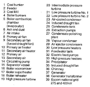
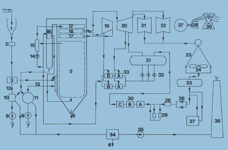
The coal delivered from Grootegeluk has a nominal calorific value of 20,5 MJ/kg and an ash content of ±36%. From the stockpile coal is transported by terrace conveyors to one of six unit silos, each with a capacity of 4650 tons. Inclined conveyor belts carry the coal from the silos to each of the five 850 ton capacity boiler mill bunkers. Two control feeders channel the coal into five rotating ball tube pulverising mills which run at 15,3 r/min and have an operating output of 100 tons per hour. Primary air fans blow the pulverized coal into 20 boiler burners per unit arranged on five levels. Forced draught fans add secondary air to aid combustion, and the mixture is then blown into the boiler furnace. The coal combustion produces coarse ash and fly ash in a ratio of approximately 1:10. The coarse ash drops to the bottom of the boiler and is conveyed away for treatment and disposal. The fly ash is carried in the flue gases to the precipitators, where more than 99% of it is removed electro-statically. Induced draught fans draw the cleaned flue gas from the precipitators and discharge it through the chimney into the atmosphere. Heat released by the burning coal is absorbed by the boiler feed water inside the many kilometers of tubing which form the boiler furnace walls. /the maximum continuous rating of each boiler at the turbine stop valve is 570 kg/s with a super heated steam temperature and pressure of 535°C and 16.1 MPa respectively. The steam passes through a super-heater to the high pressure turbine where it expands and causes the turbine to spin at a speed governed to 3 000 r/min. After exhausting some of its energy in the high pressure turbine, the steam returns to be reheated in the boiler re-heater and passed through the intermediate pressure turbine and then to the tow low pressure turbines. The generator rotor, coupled to the turbine shaft, is a cylindrical electromagnet enclosed in a gas tight housing. Electricity passes from the stator windings to a transformer which raises the voltage from 20 kV to the transmission voltage of 400kV.
COOLING AND RECIRCULATION
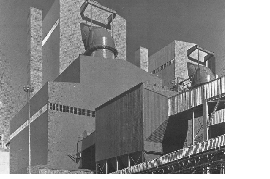
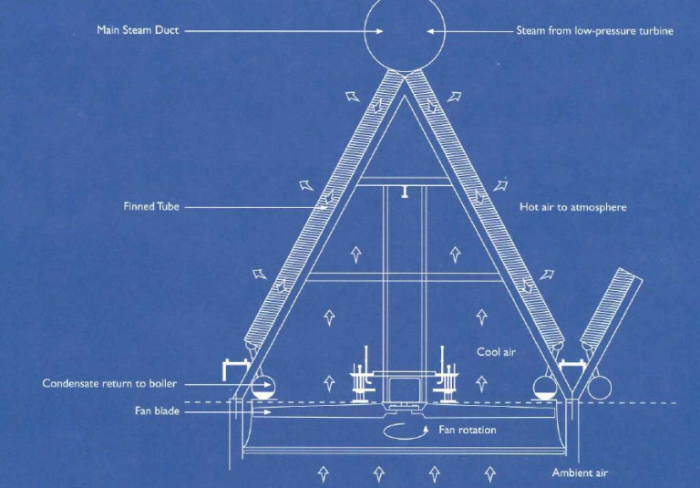
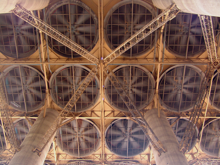
Steam from the low pressure turbines is condensed in a direct dry cooled condenser. To compensate for small losses in the steam/condensate cycle, demineralised make up water is added at this point. The condensate then passes through low pressure heaters to a deaerator and condensate storage tank. Form there three (one always in reserve) 50% electrically driven boiler feed pumps feed the water through the high pressure heaters into an economizer, where it absorbs additional hear from the flue gases before re-entering the furnace tube walls to recommence the cycle. Direct dry cooled condensers are located adjacent to the turbine house. Steam from the turbines is condensed in the finned tubing which constitutes the condensers. There is approximately 400 km of finned tubing to each condenser unit. Each condenser unit comprises eight rows of six modules each, five of which are condenser modules while on is a dephlegmator module. Where as the purpose of the condenser modules is solely to condense the steam, the dephlegmator modules also provide for the extraction of incondensable gases and air. Heat from the steam circuit is removed by air blown over the condense tubing by the forty eight 9,1 diameter forced draught fans beneath each module.
PLANT
Control
Each of Matimba’s six boiler turbine sets is operated from separate unit control rooms. From the until control room the plant process is controlled and monitored by a sophisticated process computer capable of automatically starting up and shutting down the plant through a keyboard in the unit control desk. Manual control of the plant may be carried out via pushbutton stations. Any part of the process and plant conditions can be graphically displayed on video screens.
Fuel handling
Coal crushed to less than 25 mm in size is conveyed from the Grootegeluk Colliery at a rate of up to 3 600 t/h. The maximum strategic and seasonal stockpile has a capacity of 1 200 000 tons and the live stockpile of 120 000 tons. The five mill coal bunkers per boiler have a storage capacity of 850 tons each sufficient for eight hours at full load.
Mills
Two coal feeders control the input of coal into each double ended ball tube mill, the amount being determined by the boiler steam output requirements. Inside the mills an approximately 90 ton charge of steel balls with maximum, diameters of 50 mm pulverises the coal. Primary air fans then blow the combustible pulverised fuel into the boilers at a rate of 8tons per hour. Mill reserve capacity, however, amounts to 20 tons per hour from each mill. Five mills feed coal through 20 corner mounted boiler burners into each of the six boilers. When the boiler is steaming at full load, there is one spare mill per boiler, which means that full load is achieved by using 16 burners.
Boilers
The once through boilers are the coal fired radiant furnace type with superheating and reheating. The boiler furnace walls extend to a height of 99 m and are suspended from a grid which forms the top of the 199 m high boiler house. This suspension method allows for downward expansion. Super heater and re-heater tube banks are suspended horizontally above the furnace zone of the boiler, while the economizer elements are located in the flue gas duct before the air heaters. Boiler feed water is heated to a temperature of 248°C at a pressure of 21,8 MPa before being fed to the economizer. From the economizer the water passes to the furnace walls, where evaporation is completed before outlet from the wall tubes. .
The resulting steam is collected in four steam cyclones, which also serve as the point where the steam separates from the water under start up conditions. Saturated steam is then led to the super heaters, where its temperature is increased to 540°C at about 4 MPa (abs) before passing to the intermediate pressure tube. The main steam pipe work incorporates a high pressure bypass system, which provides protection against excessive boiler pressure. It has a temperature control system, using spray attemperators to reduce the steam temperature to a value suitable for inlet into the re heaters in the event of the automatic operation of the HP bypass. The turbine piping also includes a low pressure bypass. When this system is operating, some of the condensate from the condensate extraction pumps fed to spray attemperators to cool the re heated steam before this enters the air condenser at the low pressure turbine exhaust. Use of the bypasses makes it possible to obtain the correct steam pressures and temperatures before starting up the turbo generators, and also allows the boiler to continue operating at about 45% load after the turbine has been tripped, while minimizing thermal shock on the piping systems. Each boiler is equipped with 20 burners arranged in five levels of four. Each burner has its own oil gun to start up and stabiles the pulverized fuel flame at low loads. The forced draught fans supply secondary air to the burner wind boxes, while primary air fans supply air to the coal mills to carry the air fuel mixture to the burners. Two induced draught fans draw the combustion gases from the furnace over the surfaces of the super heaters, re heaters, economizer and air pre heaters, then via the electrostatic precipitators for discharge to the chimney
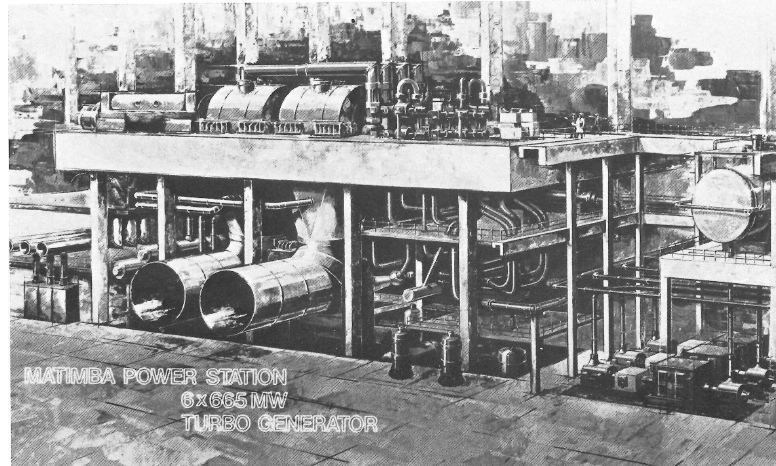
Turbines
Each of Matimba’s six sets has a high pressure cylinder, and intermediate pressure cylinder and twin double flow low pressu8re cylinders. The HP cylinder has a single flow in the reverse-direction, whereas the IP cylinder has a single flow in the normal direction. Both HP and IP cylinders are constructed with an internal and external casing to allow fast start up as well as rapid load variations.
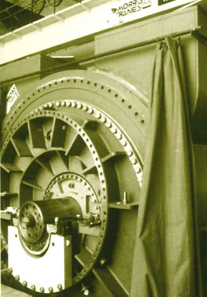
Generators
Each generator produces 665 MW at full load, with a terminal voltage of 20 kV at 50 Hz. Generator cooling as achieved in two ways. Hydrogen is circulated through the rotor at a maximum pressure of 400 kPa by two fans locked to the rotor shaft. The hydrogen is cooled via water cooled heat exchangers mounted on the generator. The stator winding is cooled by demineralised water pumped through the stator winding bars and then treated and cooled in an auxiliary plant external to the generator. The generators operate at 20 kV and their output is stepped up to 400 kV for distribution via the national grid.
Ash collection and disposal
At full load each boiler produces up to 280 tons of coarse ash and 2 500 tons of fly ash from the precipitators per day. The fly ash is conditioned to a moist cake from before being mixed with the coarse ash. The mixed ash is fed to an overland conveyor system, which transport the ash to the surface dump. Stackers spread the ash over the dump, which is eventually covered with a 200 mm layer of topsoil and then grassed.
Condensers and feed water
The condensers are of the dry cooled direct condensing type. Exhaust steam from each turbine passes through two interconnected 5 m diameter ducts to finned tube elements, located 45 m above ground level and adjacent to the turbine house. Each condenser module consists of eight bundles of cooling elements. There are 119 finned tube cooling elements in each bundle. Forced draught fans, 9,1 m in diameter and situated beneath each module, blow air over the elements to cool the exhaust steam in the finned tubing. The elements are constructed of mild steel, galvanized on the outside, with a total air side surface area of 1 200 000 m². The 48 fans rotate at 25r/min and are driven through gearboxes by single speed electric motors mounted vertically. The condensate is collected in a receiver tank inside the turbine house. One of two condensate extraction pump drives the condensate through low pressure feed heaters to the de-aerator and from there through the high pressure feed heaters. The condensate and feed water are heated in six stages by steam extracted from the turbine cylinders to a temperature of 274°C at the boiler inlet. Two variable speed pumps driven by 9,6 MW electric motors pump the feed water, while a third pump is provided as standby in the event of failure.
Cross-section of Condenser Mode
MATIMBA – PROJECT OF POWER
Near Ellilsras in the north western Transvaal a different kind of pioneer is breaking ground and establishing new frontiers among the border people. Matimba, Eskom’s giant coal-fired, dry-cooling power station, further consolidates Eskom’s position as a world leader in dry-cooling technology for power generation. The power station generates 4 000 MW, enough to provide for the energy needs of six cities the size of Durban. The dry-cooling technology is especially significant in this area of South Africa where water resources are scarce and unreliable. Dry-cooled systems consume approximately 0.4 litres/kWh compared to the 2.5 litres/kWh required by wet-cooling systems.
Statistics
Planning started in 1978
Construction started in 1981
First unit completed in 1987
Completion 1991
Six turbo-generator units will generate 4 000 MW
Six unit silos each have a 4 650 ton capacity
Five boiler mill bunkers each have an 850 ton capacity
Each of the six boilers is 100 m high
Each boiler weights 3 000 tons
There is enough space in each boiler to provide parking for 900 cars
Each boiler consumes 7 680 tons of coal per day
At full load each boiler produces up to 280 ton of coarse ash and 2 500 tons of fly ash per day
The dry-cooling technology
Matimba is the largest direct dry-cooled station in the world. Matimba uses the direct dry-cooled steam condensing system. The principle, operate in much the same way as a car radiator, where heat is conducted from the water to the metal of the radiator, and from there to the air passing through it. Exhaust steam from the turbine is conducted into the dry-cooling elements or heat exchanger. Forced draught fans drive air through the elements of the exchanger so that the heat is removed from the steam to condense it. The water which results is then pumped back to the boiler. Since this water is in a closed circuit, there is no evaporation – an advantage especially in areas where water is scarce. Evaporation losses in wet-cooling system on the Highveld can amount to as much as 1.5 million litres an hour per 600 MW wet-cooling Tower.
Approximately 80% of Matimba’s equipment will be locally manufactured. This is obviously a boon to South Africa’s industry – Matimba has in fact provided work for many people.
The fly ash produced from coal combustion is carried to electrostatic precipitators where 99% of it is removed from the flue gasses. It is then conditioned to a moist cake form and mixed with the coarse ash which has been collected at the bottom of the boiler. The mixed ash is fed onto an overland conveyor which transports the ash to the surface dump. Stackers spread the ash over the dump which will eventually be covered with a 200 mm layer of topsoil and then grassed. Trees can also be grown in pockets of soil. This allows the entire dump to be rehabilitated, so that the land is returned to its original condition.
WHAT IS DRY-COOLING AND HOW DOES IT WORK?
CONVENTIONAL COOLING
In a conventional power station the energy of steam at high temperature and pressure causes the turbines to spin and generate electricity. Exhaust steam from the turbines is converted back into water in the condensers, where it is passed over tubes containing cold water. This condensed steam is pumped back into the boiler to repeat its cycle. The water in the condensers must in turn be cooled before re-use, and this is done in the cooling tower, where the warm water is sprayed into the natural up-draught in the tower, losing its heat as it falls like rain into the pond at the base of the tower. During this process about 1.25 million litres an hour is lost in evaporation. Conventional power stations require an average of 2.5 litres of water for ever kilowatt-hour sent out – approximately 35 000 million litres of water a year for one 3 600 MW station.
The Principle of Dry Cooling
Dry-cooling adopts a principle similar to that used in the car radiator, whereby heat is conducted from the cooling water to the metal of the radiator and from there to the air passing through it. The air remains dry, since it does not come into contact with the hot water. The cooling water is closed and does not come into contact with the atmosphere – evaporation is thus almost eliminated. Water consumption in a dry-cooled power station drops to about 0.8 litres per kWh.
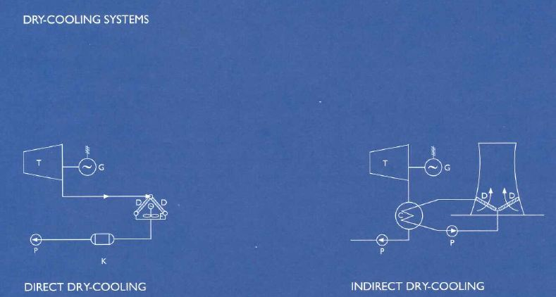
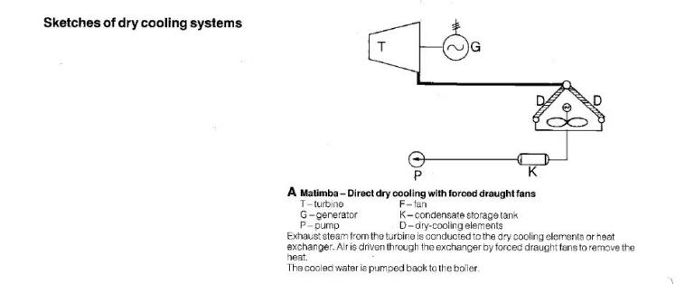
Matimba – Direct dry-cooling with forced-draught fans Kendal – Indirect dry-cooling with surface condenser
T – turbine T – turbine
G – generator G – generator
P – pump P – pump
F – fan F – fan
K – condensate storage tank D – dry-cooling elements
D – dry cooling elements C – condenser
Exhaust steam flows from the turbine to the dry-cooling Cold water flows through the condenser tubes, removing elements or heat exchanger. Air is driven through the heat from the steam which passes over them. The exchanger by forced-draught fans to remove the heat. resultant hot water is pumped through heat exchangers
The cooled water is pumped back to the boiler. inside natural-draught cooling towers.
There are two methods of dry-cooling, direct and indirect and Eskom is leading the field in world technology in introducing both on hitherto unprecedented scale in two of its newest power stations, – Matimba (direct dry-cooling).
Technical Data |
|
Generating capacity | 3 600 MW |
Fuel |
|
Mining Company | Kumba Rescources, Grootgeluk Mine, Lephalale |
Calorific value Mj/kg | Between 16 and 22 |
Moisture content – |
|
Surface normal | 9,3 (max) 4,1 (min) |
Inherent | 2,6 (max) 1,0 (min) |
Acceptable limit | 10,0 |
Ash content | ±36% |
Total annual production | 12 million tons |
Coal storage capacity |
|
Strategic and seasonal | 1 200 000 t |
Stockpiles |
|
Live stockpile | 1 200 000 t |
Unit silos (6 x 4 650 t) | 27 900 t |
Station boiler bunker capacity | 25 500 t |
Coal consumed at full load | 1 750 t/h at 90% load factor |
Milling Plant |
|
Manufacturer | Stein Industries |
Type | Horizontal ball tube type mills |
Number | 5 per boiler (30) |
Speed | 15,3 r/min |
Rated max output | 100 t/h |
Boilers |
|
Manufacturer | SIEVA |
Number | 6 |
Height | 119 m (overall) |
Maximum continuous rating | 570 kg/s |
Final steam temperature | 540ºC |
Final steam pressure | 16,1 MPa |
Steam output | 2 016 t/h |
Number of burners | 40 |
Combustion chamber volume | 17 223 m² |
Total heating surface | 225 950 m² |
Width of furnace |
|
Dimensions (plan) | 17,7 m x 17,7 m |
Furnace flame temperature | Approximately 1 500ºC |
Gas temperature at furnace exit | 1 201ºC |
Gas temperature at ID fan outlet | 130º |
Fuel consumption per year | 2 000 000 tons maximum |
Turbines |
|
Manufacturer | M.A.N.(Germany) |
Type impulse | 4-cylinder tandem |
Rating | 665 MW |
Speed | 3 000 r/min |
Steam pressure, HP inlet | 16,1 MPa |
Steam pressure HP inlet | 16.1 MPa |
Steam pressure HP inlet | 535ºC |
Steam pressure IP inlet | 3.69 MPa |
Steam temperature IP inlet | 535ºC |
Exhaust steam back pressure | 19.8 kPa (yearly average) |
Generators |
|
Manufacturer | Alsthom Atlantique (France) |
Rating | 739 MVA |
Rated capacity | 665 MW |
Terminal voltage | 20 kV 50 Hz |
Power factor | 0.9 lagging |
Cooling medium: |
|
Stator core and rotor | Hydrogen at 250 kPa (normal) |
| 400 kPa (maximum) |
Stator winding | Demineralised water |
Generator transformers |
|
Manufacturer | ASEA Electric |
Rated capacity | 700 MVA |
Terminal voltage | Primary 20 kV |
| Secondary 420 kV |
Cooling system |
|
Manufacturer | GEA Air-cooled Systems (Germany) |
Number of systems | 6 |
Type | Forced-draught direct condensing |
Annual energy rejection | 7 500 GWh |
Plot area of condenser | 6 000 m² |
Air side surface area | 120 ha |
Mass flux | 33 500 kg/s |
Overall dimensions of platform |
|
Width | 85 m |
Length | 72 m |
Height above ground | 45 m |
Number of fans | 48 per unit |
Fan diameter | 9.2 m |
Diameter of main Steam ducts | Approximately 5 m |
Chimneys |
|
Manufacturer | CONCOR Construction (Pty) Ltd |
Number | 2 |
Type | 3 flues with windshield |
Height | 250 m |
Top diameter | 21.1 m |
Base diameter | 22.7 m |
Main Contractors |
|
Earthworks | LTA Construction (Pty) Ltd |
Civil Engineering | CONCOR Industrial (Pty) Ltd |
Steelwork (subcontractor) | GENREC (Pty) Ltd |
Boilers | SIEVA (Pty) Ltd |
Turbine generators | M.A.N (Germany) Altshom (France) |
Generator transformers | ASEA Electric (SA) Ltd |
Chimneys 1&2 | CONCOR Industrial (Pty) Ltd |
Main station cabling | Industrial Electrical (Pty) Ltd |
Unit control and Instrumentation | Siemens Ltd |
Fire protection system | C.I.W (Pty) Ltd |
Coal handling on terrace | LTA MITEC |
Coal stockyard conveyor system | Bateman Engineering Ltd |
Ash conveyor system | Babcock Moxey |
Dust-conditioning plant | Babcock Claudius |
Auxiliary cooling system | Hamon Sobelco |
Sewage plant | Aquazur Reunert (Pty) Ltd |
Electrostatic precipitators | Simon Carves Africa |
Water treatment plant | Simon Carves Africa |
Direct dry-cooling systems | GEA Air-cooled Systems |

Direct Dry Cooling
Team from the low-pressure turbine is channeled directly into the radiator-type heat exchanger. Air passing through the exchanger removes the heat, thus condensing the steam into water to be pumped back to the boiler.
The flow of cooling air through the exchangers is assured either by natural draught in cooling towers or by forced draught using fans.
Indirect Dry-Cooling
The indirect system makes use either of surface condensers as in conventional wet-cooled power stations, or of jet condensers. In the firmer, cold water flows through the tubes of the condenser, removing heat from the steam passing over the, This now heated water then flows through heat exchangers arranged inside a natural draught cooling tower. In the alternative jet-condenser system, exhaust steam leaving the low-pressure turbine is condensed by a spray of cold water. The resultant hot water collects in a ump and is pumped through the heat exchangers in the cooling towers.
Optimum use of Coal and Water
Constant research has enabled Eskom to reduce its coal consumption to as little as 0,533 KG/KwH sent out. This is especially noteworthy considering the low grade of the coal burned (calorific value between 18 and 22 MJ/kg; ash content ±35%). Not only does Eskom burn coal for which there is no other use, but in so doing it saves millions of tons of better quality coal for export or for specialised industrial use. The Grootegeluk Colliery, which provides ISCOR with high grade metallurgical coal for iron and steel production, is this able to send the waster low grade coal to Eskom. This in effect makes Matimba part of a joint venture which assures maximum beneficiation of the colliery. Ongoing studies to increase the efficiency of water consumption have reduced this figure to 2,02 litres per kWh sent out. (Matimba has already achieved 0,16 litres per kWh and less). The decision to build dry cooling power stations is a further step in the conservation of our country’s limited water supplies.
Dry Cooling vs Wet Cooling
Although the expense involved in the construction and operation of a coal fired power station with a dry cooling system is greater than that of one with a wet cooling system, limited available water resources may override economic considerations in determining the choice between the two technologies. Dry cooled systems consume less than 0,2litres/kWh. Compared with the 2,0 litres/kWh required by wet cooled systems. Evaporation losses in wet cooling systems account for approximately 80% of the water requirements of a conventional wet cooled power station. These losses can amount to 1,5 million litres an hour per 600 MW wet cooling tower on the South African Highveld. The choice of dry cooled technology for Matimba was heavily influenced by the severe shortage of water in the area.
Dry Cooling Technology
These are two basic dry cooling systems. The indirect dry cooling system adopts a principle similar to that used in the car radiator, where heat is conducted from the water to the metal of the radiator and from there to the air passing through it. The air remains dry, as it does not come into contact with the hot water. The water is in a closed circuit and evaporation is this minimized. In the direct system steam from the low pressure turbine is channeled directly into the radiator type heat exchanger. The heat is conducted from the steam to the metal of the exchanger. Air passing through the exchanger removes the heat, thus condensing the steam into water to be pumped back to the boiler. Cooling in both the direct and indirect systems can be achieved either by natural draught in cooling towers or by forced draught using fans. Cooling in the Matimba direct dry cooling system, however, is by forced draught, whereas an indirect natural draught system is applied at Kendal power station. The indirect system makes use either of surface condensers as in conventional wet cooled power stations, or of jet condensers. In the former, cold water flows through the tubes of the condenser, removing heat from the steam passing over them. This now heated water flows through heat exchangers arranged inside a natural draught cooling tower. Air to cool the water is drawn through the tower and across the heat exchangers either by natural convection or by electrically driven fans. In the alternative jet condenser system, exhaust steam leaving the low pressure turbine is condensed by a spray of cold water. The resultant hot water collects in a sump and is pumped through the heat exchangers in the cooling towers as in the surface condenser system. In addition, part of the condensed water is led from the sump of the jet condenser to the boiler. The main advantage disadvantages of this system are the large volume of highly purified water required and the problem of ensuring that no air can leak into the system. The performance of a dry cooling system depends on the ambient dry bulb temperature. Temperatures at Ellisras vary as much as 15 degrees from day to night and in summer will frequently rise to the 40s. Consequently the rate at which the air draws heat from the heat exchangers will vary considerably, as will the back pressure at the turbine exhaust. This will affect the efficiency of the turbines in such a way that the rated 665 MW might only be achieved when ambient air temperatures are low.
Planning
The planning of Matimba as a base load station began in 1978. The six 665 MW turbo generator units make it the largest direct dry cooled station in the world, followed by the single 365 MW unit at Wyodak in the United States. Annual set out power is approximately 20 000 GWh, with a weighted annual average turbine back pressure of 19,8 kPa. Construction started in mid 1981 and the first unit was placed on commercial load in September 1987.
The Basic Cycle
The coal delivered from Grootegeluk has a nominal calorific value of 20,5 MJ/kg and an ash content of ±36%. From the stockpile coal is transported by terrace conveyors to one of six unit silos, each with a capacity of 4650 tons. Inclined conveyor belts carry the coal from the silos to each of the five 850 ton capacity boiler mill bunkers. Two control feeders channel the coal into five rotating ball tube pulverising mills which run at 15,3 r/min and have an operating output of 100 tons per hour. Primary air fans blow the pulverized coal into 20 boiler burners per unit arranged on five levels. Forced draught fans add secondary air to aid combustion, and the mixture is then blown into the boiler furnace. The coal combustion produces coarse ash and fly ash in a ratio of approximately 1:10. The coarse ash drops to the bottom of the boiler and is conveyed away for treatment and disposal. The fly ash is carried in the flue gases to the precipitators, where more than 99% of it is removed electro-statically. Induced draught fans draw the cleaned flue gas from the precipitators and discharge it through the chimney into the atmosphere. Heat released by the burning coal is absorbed by the boiler feed water inside the many kilometers of tubing which form the boiler furnace walls. /the maximum continuous rating of each boiler at the turbine stop valve is 570 kg/s with a super heated steam temperature and pressure of 535°C and 16.1 MPa respectively. The steam passes through a super-heater to the high pressure turbine where it expands and causes the turbine to spin at a speed governed to 3 000 r/min. After exhausting some of its energy in the high pressure turbine, the steam returns to be reheated in the boiler re-heater and passed through the intermediate pressure turbine and then to the tow low pressure turbines. The generator rotor, coupled to the turbine shaft, is a cylindrical electromagnet enclosed in a gas tight housing. Electricity passes from the stator windings to a transformer which raises the voltage from 20 kV to the transmission voltage of 400kV.
Cooling and Recirculation
Steam from the low pressure turbines is condensed in a direct dry cooled condenser. To compensate for small losses in the steam/condensate cycle, demineralised make up water is added at this point. The condensate then passes through low pressure heaters to a deaerator and condensate storage tank. Form there three (one always in reserve) 50% electrically driven boiler feed pumps feed the water through the high pressure heaters into an economizer, where it absorbs additional hear from the flue gases before re-entering the furnace tube walls to recommence the cycle. Direct dry cooled condensers are located adjacent to the turbine house. Steam from the turbines is condensed in the finned tubing which constitutes the condensers. There is approximately 400 km of finned tubing to each condenser unit. Each condenser unit comprises eight rows of six modules each, five of which are condenser modules while on is a dephlegmator module. Where as the purpose of the condenser modules is solely to condense the steam,the dephlegmator modules also provide for the extraction of incondensable gases and air. Heat from the steam circuit is removed by air blown over the condense tubing by the forty eight 9,1 diameter forced draught fans beneath each module.
MATIMBA – PROJECT OF POWER
Near Ellilsras in the north western Transvaal a different kind of pioneer is breaking ground and establishing new frontiers among the border people. Matimba, Eskom’s giant coal-fired, dry-cooling power station, further consolidates Eskom’s position as a world leader in dry-cooling technology for power generation. The power station generates 4 000 MW, enough to provide for the energy needs of six cities the size of Durban. The dry-cooling technology is especially significant in this area of South Africa where water resources are scarce and unreliable. Dry-cooled systems consume approximately 0.4 litres/kWh compared to the 2.5 litres/kWh required by wet-cooling systems.
Statistics
Planning started in 1978
Construction started in 1981
First unit completed in 1987
Completion 1991
Six turbo-generator units will generate 4 000 MW
Six unit silos each have a 4 650 ton capacity
Five boiler mill bunkers each have an 850 ton capacity
Each of the six boilers is 100 m high
Each boiler weights 3 000 tons
There is enough space in each boiler to provide parking for 900 cars
Each boiler consumes 7 680 tons of coal per day
At full load each boiler produces up to 280 ton of coarse ash and 2 500 tons of fly ash per day
Milestones
Matimba has broken a number of records right from the start:
In 1996 Matimba broke the world record for six units on load. These ran continuously for 80 days – a record still held by Matimba today.
In 2000, Matimba was the joint winner of the Jan H Smith Trophy awarded by Eskom for top performances in leadership and management excellence.
On 8 February 2001. Unit 4 ran on full load for 389 days, 19 hours abd 16 minutes – making it the longest single unit continuous run within Eskom. (This record has since been surpassed by Koeberg Nuclear Power Station).