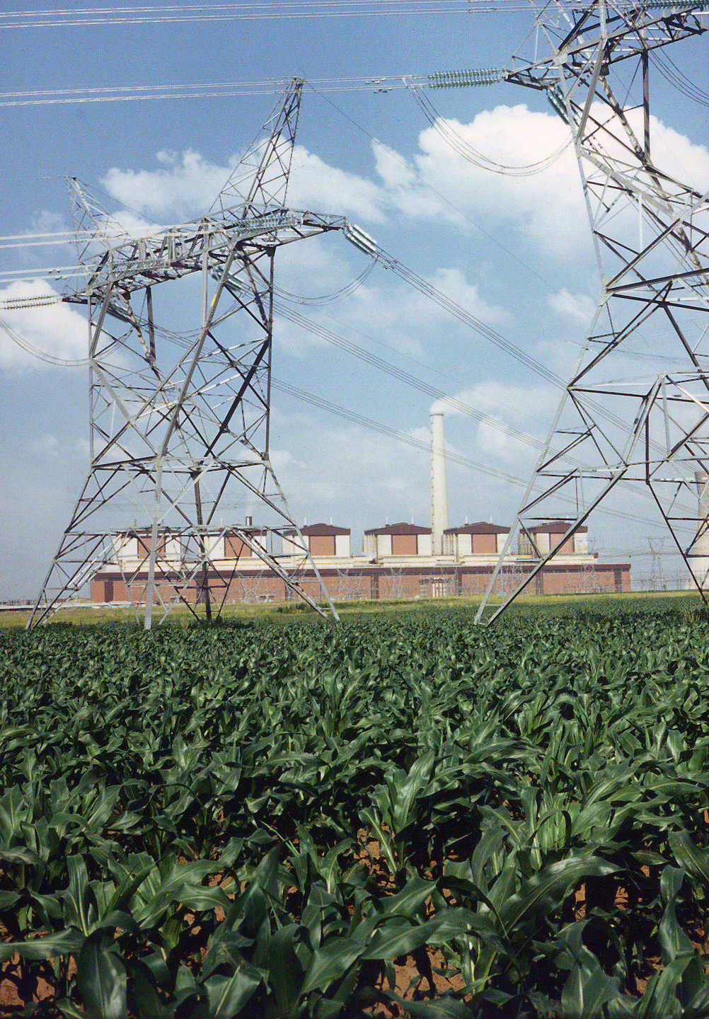
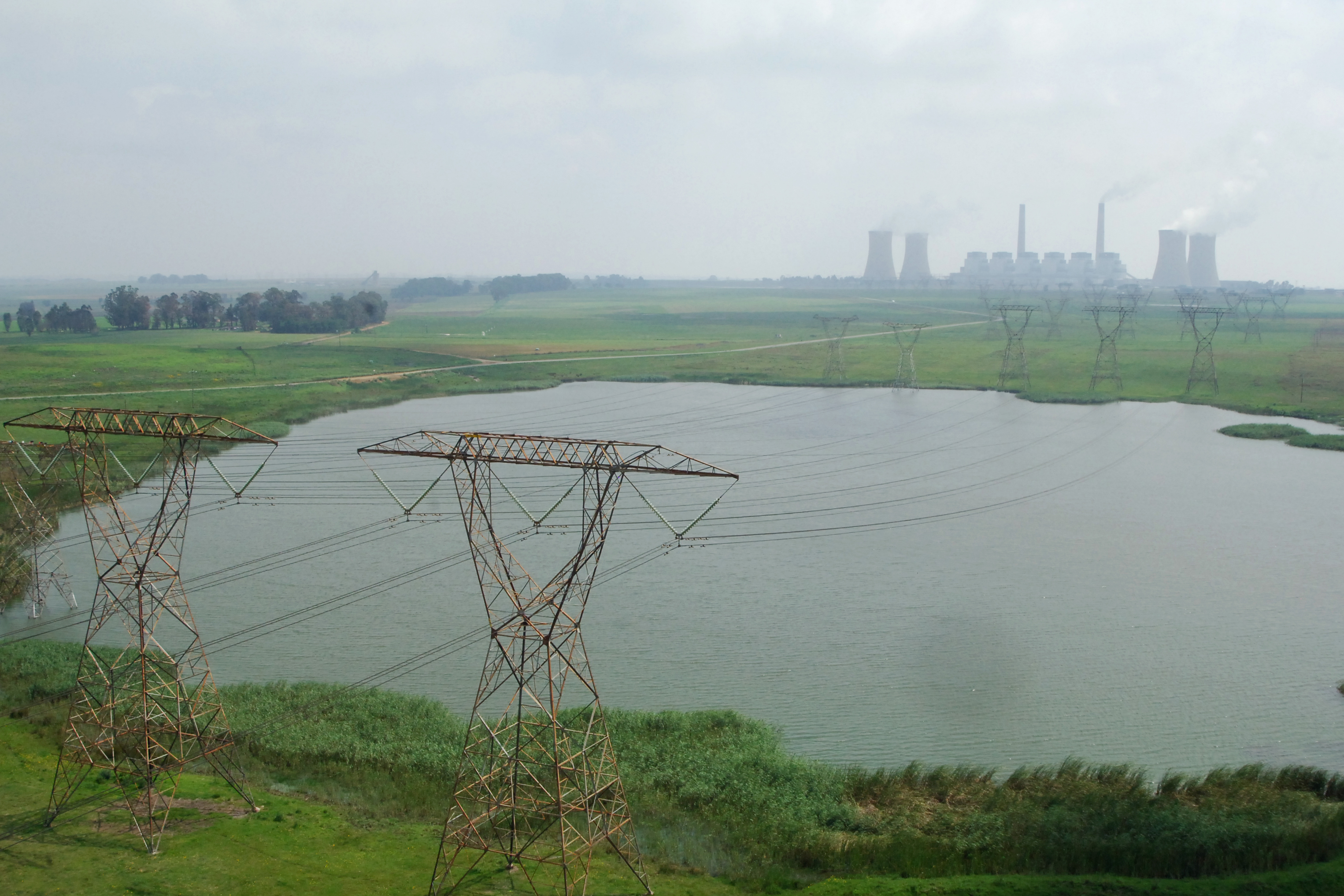
Matla Power Station
INTRODUCTION
MATLA a Sotho word meaning “strength” or “power”, has taken on a new meaning in the Eastern Transvaal now Mpumalanga. The coal-fired power station bearing this name, is located near Kriel on the Mpumalanga Highveld about 200 km from Johannesburg. The word is now associated with electrical power and a massive 3 600 MW power station Matla when completed, was the biggest power station in South Africa (the first using 600 MW turbo-generators) and one of the largest in the world. Matla was the first of the giant 3 600 MW coal-fired power stations in the world with a concrete boiler house superstructure. This gives it a robust appearance, which is very different from that of other power stations in South Africa. The unusual design evolved as a result of a world-wide steel shortage during the design stages. The planning and design of Matla power station commenced in the early 1970s. It was designed for an operating life of 30 years, but substantial coal reserves have extended its life span to 50 years. The station consists of six 600 MW units, giving an installed capacity of 3 600 MW. Matla’s power is fed into both the 400 and 275 kV networks. Construction commenced in 1976, and the station was fully commercial by July 1983.
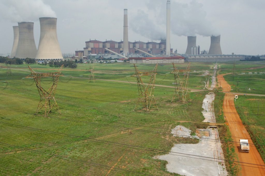
The planning and design of Matla began early in the seventies. Construction started late in 1974 and the station was scheduled for completion before Eskom’s winter peak-demand period in mid-1983. The first of the six 500 MW sets started feeding power into the national grid towards the end of 1979. Matla had been designed for an operating life of 30 years, but substantial coal reserves may give it a lifespan closer to 50. As a base load plant it will operate continuously except for regular scheduled stoppages on individual sets for inspection and maintenance. A total of 3 800 tons of coal per hour can be transported by conveyor to the power station from the adjacent Matla colliery, which mainly makes use of long wall retreating mining methods. Because the coals seams are at an average depth of between 48 and 105 metres, opencast mining methods will not be used. Roughly 90 per cent of the reserves will be extracted.
Matla is a six pack power station
It has six 2 pole, 3 000 r/min synchronous generators, each with a rating of 688,9 MVA, 20 kV. The generators stators are water-cooled and their rotors are hydrogen-cooled. Power from each generator is transferred to the national electricity grid by means of an oil-cooled 700 MVA generator transformer. Two generator transformers are designed to step up the voltage from 20 kV to 400 kV, and the remaining four are designed to step up the voltage from 2o kV to 275kV. For each unit there is a 20 kV breaker between the generator and generator
The coal consumption of Matla power station is approximately 1,150 000 tons per month. A total of 3 800 tons of coal per hour can be transported to the power station by conveyor from the adjacent Eyesizwe Matla Colliery, which employs mainly long wall-retreating mining methods. Because the coal seams are at an average depth of between 48 and 105 metres, open-cast mining methods are not used. Roughly 90% of the reserves will be extracted.
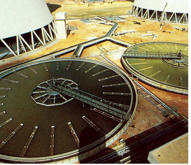
Water supply
The raw water used at Matla was initially supplied by Kriel power station, but since the completion of the Vaal River system water has been supplied by the Grootdraai Dam, Grootfontein pump station and Rietfontein weir pump station. Matla power station raw-water consumption is about 3 500 Ml (megalitres) per month.At full load, the six units at Matla require 3 500 Ml of water per month.The bulk of this is used to make up for water lost by evaporation through the cooling towers.
Other uses include cooling system blow downs, demineralised water makeup to the condense circuit, ad portable water for site drinking and domestic use.
The raw water for Matla is obtained from the Vaal and Usutu river systems. The Vaal supply is relatively plentiful, but the water normally contains a high content of suspended and dissolved solids. This increases the costs of water treatment and de-mineralization.
Usutu water is substantially cleaner than Vaal water, but its supply to Matla depends on the consumption by Kriel and Kendal power stations. Because it contains less suspended and dissolved solids. Usutu water costs less than Vaal water to treat particularly to demineralise. Although Usustu water has a lower unit cost for both supply and treatment than Vaal water. Eskom’s allocation of this water is insufficient to meet Matla’s needs. The shortfall is therefore made up by using Vaal water.
Fuel handling
The coal from Matla mine is delivered, crushed to less than 25 mm in size, to the two coal staithes at 3 800 tons per hour. The overland conveyor system is roughly 2 km long. Each boiler has six coal bunkers. The coal bunkers are concrete structures with a stainless steel lining. Coal is stored in two coal staithes before being passed to the boilers for burning. The first staithe, with a capacity of 50 000 tons, serves boilers 1 to 4, and the second with a capacity of 30 000 tons, serves boilers 5 and 6.
The coal is drawn from the staithes and conveyed via a series of belts to the coal bunkers situated next to each of the boilers. The bunkers have an approximate capacity of 1 000 tons, and there are six bunkers per boiler, giving an effective storage capacity at the boilers of 18 hours operation at full load.Each bunker feeds coal to a dedicated mill, via a coal feeder, through a gravity feed from the bunker to the feeder. When a boiler is started up, fuel oil is used as support for the coal, until the combustion of the pulverised coal is stable. The fuel oil is stored in four storage tanks with a combined capacity of 5400 kl.
Milling plant
The milling plant consists of a volumetric coal feeder, a vertical spindle mill, a classifier and the piping to transport the milled coal (PF) as well as 8 burners. The speed-controlled, coal feeder, delivers raw coal from the bunker to the mill to yield the desired quantity of coal to the boiler. The coal falls by gravity from the feeder to the mill and is pulverised the grinding elements. An integral part of the mill is its classifier, which can be adjusted to obtain the required degree of fineness of the pulverised coal leaving the mill.
The primary air fan delivers clean, hot, high-pressure air to the mill. This air can be controlled in quantity and temperature. It’s main purpose is to dry the coal and to transport pulverised fuel (PF) to the burners. The primary air delivers the PF to the burners through PF piping, the burners receive the PF/ primary air mixture, and the combustion of the coal is promoted by the addition of hot secondary air. There are six mills per boiler, five on load and one on standby under full load conditions, for which approximately 280 tons of coal per hour are required depending on the quality of the coal.
Turbines
Each of the six turbines unit has a high-pressure (HP) and an intermediate-pressure tandem configuration. Each turbine operates at a rotational speed of 3 000 r/min. The HP and LP cylinders have an internal and external casing to stablise temperature gradients, thus allowing for fast start-up and rapid load variation.
Live steam at a temperature of 535ºC and a pressure of 16.1MPa is admitted into the HP turbine via the HP steam stop an control valves. It expands through the 10 HP stages, producing approximately 30% of the total power output. Spent steam from the HP turbines is returned via the cold reheat piping system to the re heater part of the boiler, where its temperature is raised to 535ºC at a pressure of about 3.7MPa. It then enters the IP turbine and expands via nine stages to reach 264ºC and 0.47MPa pressure.
During expansion in the IP modules, some steam is bled off to preheat feed water and thus to reduce the boiler heat input. A thrust bearing is employed between the HP and IP cylinders to absorb the residual thrust from the rotors.
From the IP turbine exhaust, the team is carried into the LP cylinders via large crossover pipes one to each LP cylinder. On entering the LP cylinder, the flow of steam splits nearly equally and expands in two directions through six stages on each side. The steam becomes sub-atmospheric at about the penultimate stage, and the last stage handles wet steam with roughly 8-9% moisture. The last-stage blade, which is approximately 1 080 mm long and one of the largest for a machine of this speed, has an average tip velocity of 510 m/s at full speed. The steam is expelled at an axial velocity of 240 m/s through a bell-mouth exhaust leading to the condenser neck. Condensation takes place at a back pressure of about 5 kPa (abs) in the dual-pressure surface-type condenser.
Feed-heating plant
At the design point the condensate temperature in the condensate temperature in the condenser hot well is 34,3ºC. Maximum system efficiency is obtained by preheating the condensate through three LP heaters and four HP heaters. The FWT and LP pre-heaters are of the surface type, in which water flows through tube nests. Steam extracted from different staged of the turbine heats the water by means of conduction through the tube metal.
A spray-type de aerator between the low-pressure and high-pressure heaters removes entrained air in the condensate and heats the water by direct contact with steam extracted from the turbines. The condensate is pumped from the condenser to the spray-type de aerator through the low-pressure heaters by the main condensate extraction pumps. The feed water is then passed through high pressure heaters, reaching the boiler at a temperature of approximately 247ºC.
Condensers
The condensers are of the dual pressure surface type. The vacuum inside the condensers is established by steam jet ejectors and maintained in normal operation by water jet air ejectors. Steam exhausted from the LP cylinder condenses over 32 856 brass tubes with a surface area of 23 400 m². Each boiler turbine set has a dual condenser with a heat exchange capacity approximately 2 x 400 MW.
Boilers
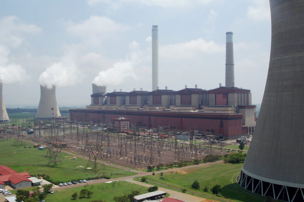
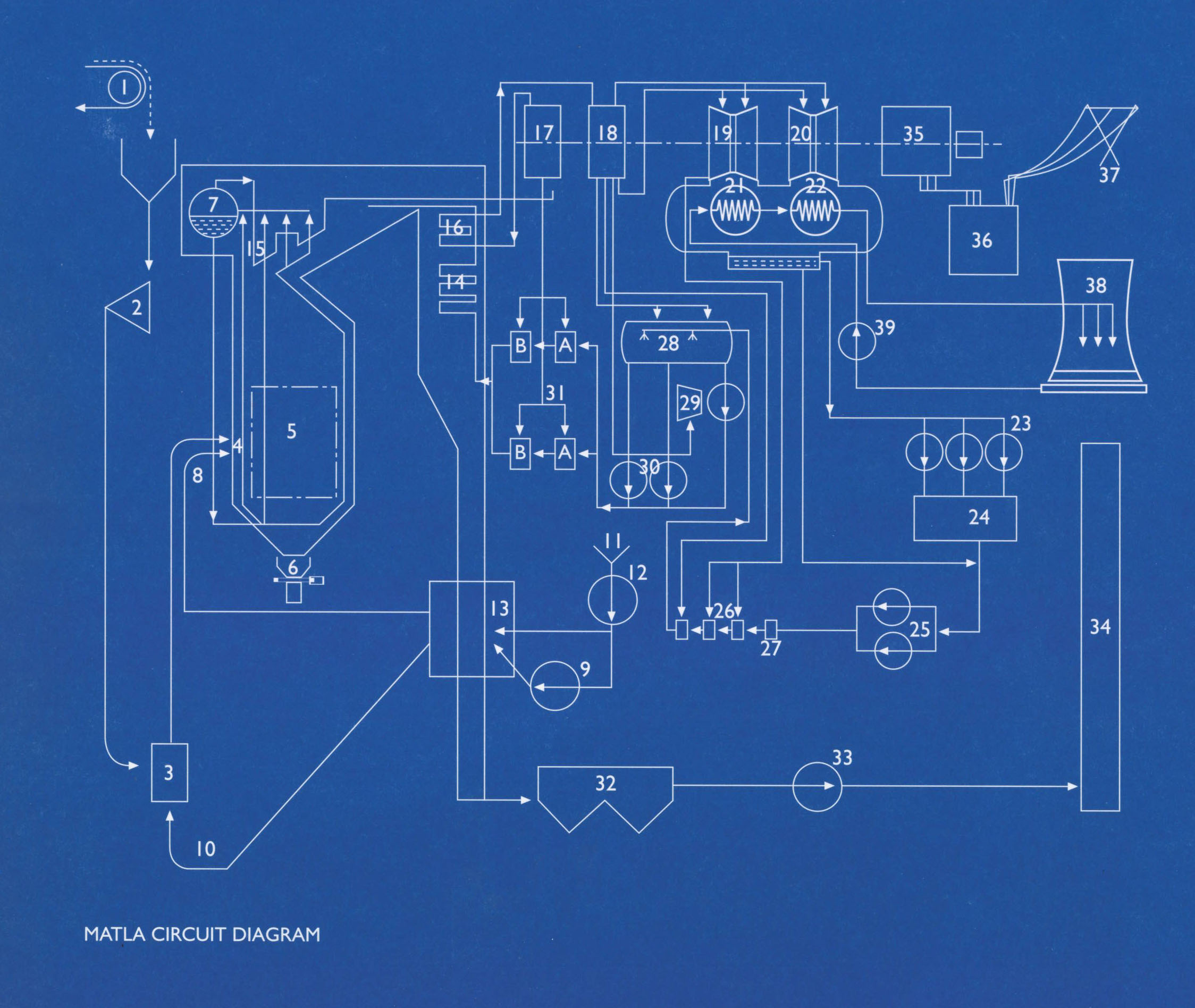
Matla is one of the few power stations in the world with a concrete boiler house superstructure, giving it a robust outward appearance very different from other stations in South Africa. The rather unusual design evolved as a result of a worldwide steel shortage during the initial design stages. The use of concrete resulted in a reduction in the construction lead time and in savings in capital outlay. The six boilers are of the coal fired radiant furnace, natural circulation type with rehearing. Each 65 m high boiler is suspended from the top of the boiler house to overcome expansion problems. Highly purified demineralised water circulates upwards within tubing making up the boiler furnace walls. Heat is transferred to this water within the furnace wall tubes, and boiling results. The steam and water mixture produced is collected in a steam drum (on the 65m level in the boiler house) where the steam separates from the water. Saturated steam is then led to the super-heaters where it absorbs more heat the temperature of the steam being increased to 540°C at a pressure of almost 17 MPa (abs). Superheated steam is used to drive the turbines which in turn spin the generator rotor coupled to the turbine shaft. The main steam pipework incorporates a high-pressure bypass system by means of which steam can be made to bypass the high-pressure turbine and flow directly into the cold rehear pipework. After passing through the re heaters into the hot reheat-pipework, the steam passes through the low pressure bypass system and discharges into the main condenser after passing through spray de-super-heaters. The bypass systems are designed to handle 35 per cent of the boilers’ maximum rated flow and are installed for the following reasons:
to obtain the correct steam pressure and temperatures before starting-up the turbo generators, and to allow the boiler to continue operating on a low load after the turbine has been tripped.
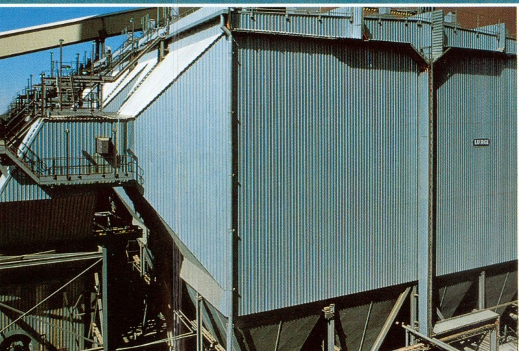
Each boiler is equipped with 48 burners arranged in three rows of eight on both front and rear furnace walls. Mounted in the centre of each burner is an oil burner which is used for starting up and for stabilizing the pulverized fuel flame at low loads. The constant speed forced draught fans supply secondary air to the burner wind boxes whilst primary air fans supply primary air to the coal mills to carry fuel to the burners. Combustion gases are drawn from the furnace by two induced draught fans, over the surfaces of the steam super- heater, the economizer, air pre-heaters and via the electrostatic precipitators to the chimney. Approximately 99 per cent of the dust, or fly ash, is collected by the precipitators.
Plant
Control: There are three control rooms, each serving a pair of sets. Each boiler-turbine set will be run as a separate entity, with controls and instrumentation accordingly incorporated into individual unit control desks and panels. From here all major operations associated with start-up, normal operation, shutdown and emergency operation can be carried out. These control rooms are in constant touch with other major nerve centres making up the integrated Eskom transmission network. The control room of set 1 also accommodates the high voltage yard monitoring and operating functions. A data logging computer constantly monitors the main operating and alarm systems, providing operating personnel with a constant flow of information on video screens and printouts.
Mills
Each pulverized fuel mill is fed by a coal feeder which controls the flow of coal into the mill, the amount being determined by the boiler steam output requirements. AS the coal enters the mill it is ground to a fine powder by steel balls running in a circular track, then discharged into the boiler by means of an airflow supplied by the primary air fan. When working at full capacity each mill crushes about 75 tons of coal per hour. There are 36 mills in all providing a spare capacity of 2 mill per boiler when design quality coal is being burned. At full load, each boiler burn about 250 tons of coal per hour.
Ash collection and disposal
When on full load, each boiler produces 250 tons of coarse ash and 1 400 boiler tons of dust per day. The total quantity of ash and dust produced by the six sets will amount to some 10,000 tons daily.
Dust collected in the precipitator hopers is sluiced away to an ash sump (on per boiler). During de ashing, coarse ash and mill rejects are sluiced to ash crushers, and then fed into set ash sumps. The dust/ash slurry is pumped from the sumps to ash dams. All water used to convey the ash is decanted from the ash dams and returned for reuse in the ash system in a closed cycle.
Generators
Each generator coupled to the end of the LP turbine shaft generates 600 MW at full load at the terminal voltage of 20 kV. Generator cooling is done in two ways using hydrogen and demineralizer water. The stator and rotor are pressurised to a maximum pressure of 500 kPa by means of hydrogen which is circulated through coolers by 2 fans solidly locked to the main shaft.
The coolers are of the surface type and cooled by circulating water. A circulating demineralized water cooling system assists the hydrogen cooling generators of units 1 and 2 feed the 400 kV grid, while the four remaining generators will feed the 275 kV network.
High-voltage yard
The 400 kV yard consists of a three bus-bar system with one transfer bay, two bus coupler bays and one bus section bay. The 275 kV yard consists of a two-bus bar system with two bus coupler bays and two bus section bays. The outdoor yard layout at Matla allows for the interconnection of the 400 kV system with the 275 kV grid by means of coupling transformers.
Technical Data | |||
Generating capacity | 3 600 MW | ||
Mining company | Eyesizwe | ||
Fuel | |||
| |||
Calorific value | 24 MJ /kg (dry basis) | ||
Ash content | 19.10% | ||
Sulphur content | ±1% | ||
Coal consumed at full load | ±1800 tons/h | ||
Total annual consumption | ±13-14 million tons | ||
Coal staithe capacity | 80 000 tons | ||
Staithe 1 | 50 000 tons | ||
Staithe 2 | 30 000 tons | ||
Stockpile capacity | 28 million tons | ||
Boiler bunker capacity | 7 000 tons per boiler | ||
Fuel oil – Bunker | 150 | ||
Storage capacity | 2000 tons | ||
Annual consumption (total) | ±3 000 KI | ||
Boilers | |||
Number | 6 | ||
Manufacturer | Babcock | ||
Type | Natural circulation | ||
Height (roof to hopper) | 62m | ||
Maximum continuous rating | 508 kg/s | ||
Final steam pressure | 17.2 MPa | ||
Final steam temperature | 540ºC | ||
Re heater steam pressure | 3.84 MPa | ||
Re heater steam temperature | 540ºC | ||
Width at burner level | 24m | ||
Depth at burner level | 13.7 m | ||
Boiler expansion (downwards) | 280 mm | ||
Boiler water content cold | 122400 kg | ||
Furnace volume | 12193 m² | ||
Total heating surface area | 6008 m² | ||
| |||
| |||
Boiler circulation pump | None | ||
Cooling Towers | |||
Number | 6 | ||
Type | Concrete construction natural draught | ||
Overall dimensions | |||
Height | 149 m | ||
Diameter at base ring beam | 98.25 m | ||
Pond diameter | South 107.3 m – North 94.6 m | ||
Depth of pond | South 1.58 m – North 1.75 m | ||
Capacity of tower pond | 14300 m³ | ||
Throat diameter | 54.62 m | ||
Diameter at top | 61.03 m | ||
Air inlet area | 2 317 m² | ||
Evaporation at 600 MW | 1 250 m³/h | ||
Chimneys | |||
Number | 2 | ||
Height – 273 M north, multi-flue | 213 M south | ||
273 M north, multi-flu | |||
Diameter (base) | 25 M base South | ||
28 M base North | |||
Diameter: (top )ID | |||
14 M top South | |||
28 M top North | |||
Turbines | |||
Manufacturer | MAN | ||
Type | Multi-cylinder impulse reaction | ||
Speed: | 3 000 r/min | ||
Steam flow to HP turbine | 492 kg/s at MCR | ||
HP Exhaust steam flow to RH: | 462 kg/s | ||
Work rate of HP cylinder: | 30% or 180 MW | ||
HP cylinder blading efficiency: | 89.20% | ||
Steam flow to IP Turbine | 462 kg/s at MCR | ||
Work rate of IP cylinder | 50% or 300 MW | ||
IP cylinder blading efficiency | 93% | ||
Steam flow to LP 1 | 188.4 kg/s | ||
Steam flow to LP 2 | 188.4 kg/s | ||
Work rate of LP 1 & 2 | 20% or 120 MW | ||
Total work rate of turbine train | 600 MW | ||
Total efficiency | 43% | ||
Mills | |||
Manufacturer | Babcock & Wilcox (SA) | ||
Type | E 12.9 vertical spindle | ||
Number | 6 per boiler | ||
Rotational speed | 26.7r/min | ||
Rated output | 70 tons/hr | ||
Motor | 683 kW | ||
Feeders | |||
Manufacturer | |||
Number | |||
Minimum coal throughput | Stock equipment | ||
Maximum coal throughput | 6 per boiler | ||
Throughput control | 15 tons/hr | ||
75 tons/hr | |||
Variable speed DC 380 V motors | |||
Forced-draught fans | |||
Manufacturer | James Howden & Co Ltd | ||
Type | Z design 6 | ||
Number | 2 per boiler | ||
Volume flow per boiler (design) | 576m³/s | ||
Mass flow per boiler (design) | 720kg/s | ||
Impreller shaft coupling | Wellman Bibby | ||
Motor output | 2000 kW | ||
Motor speed | 745 RPM | ||
Gas-control method | Vane inlet control system | ||
Condenser | |||
Type | Dual pressure surface | ||
Cooling principle | Conduction | ||
Type and number of tubes | 30556 Admiralty brass | ||
2300 Titanium | |||
Total tube surface area | 23400 m² | ||
Condenser pressure | 5.6 and 8,3kPa (abs) | ||
Condenser steam pressure | 42ºC | ||
Condenser steam flow | 165.3 x 2 kg/s | ||
Extraction pumps | |||
Motor manufacturer | GEC | ||
Power output | 1600 kW | ||
Speed | 1450 r/min | ||
Pump manufacturer | Mather and Platt | ||
Type | 400-600 | ||
Delivery pressure | 98kPa | ||
Delivery pressure | 1668kPa | ||
Load pressure feed heaters | |||
Bled steam temperature | No 1 – 77.3ºC | ||
No 2 -159.4ºC | |||
No 3 – 264.5ºC | |||
Water inlet temperature | No 1 – 39.4ºC | ||
Water outlet temperature | No 1 -74.1ºC | ||
No 2 – 110.3ºC | |||
No 3 – 146.4ºC | |||
Steam safety valve | No 3 – 3.70kPa | ||
Water safety valve | 3000kPa | ||
De-aerator | |||
Steam pressure | 961kPa | ||
Safety valve | 1100kPa | ||
Water temperature | 176ºC | ||
Boiler feed pumps (electric) | |||
Manufacturer | Sulzer | ||
Number | 2 per unit | ||
Type | Multistage | ||
Discharge capacity | 300kg/s | ||
Discharge pressure | 19.5MPa (abs) | ||
Motor power output | 9800 kW | ||
Motor speed | 1492 r/min | ||
Main pump speed | 5000r/min | ||
PA Fans | |||
| |||
Manufacturer | Hwden SA Fan Co | ||
Number | 6 per unit | ||
Type | Single inlet type | ||
Coupling | Wellman Bibby | ||
Motor | 3,3 kV squirrel-cage induction | ||
Motor output | 2050 kW | ||
Motor speed | 1488 r/min | ||
Fan delivery temperature | 50-250ºC | ||
Fan delivery pressure | 15-12kPa | ||
Pulverised fuel burners | |||
Number | 48 per boiler | ||
Fuel oil burners | |||
Number | 48 per boiler | ||
Delivery capacity (each) | 650 kg/h | ||
Re heaters | |||
Type | Convective | ||
Heating surfaces | 13602 m² Primary | ||
7900 m² Secondary | |||
Protection | 8 safety valves | ||
Total discharge capacity | 540 kg/s | ||
Super heaters | |||
Number | 3 per boiler | ||
Type | One radiant and two convective | ||
Heating surfaces | 3655m² Primary | ||
1790m² Platen | |||
3824 m² Secondary | |||
Protection | 4 safety valves | ||
Total discharge capacity | 168kg/s | ||
Economiser | |||
Type | Plain tube | ||
Heating surface | 15690 m² | ||
Steam drum | |||
Length | 24 metres | ||
Inside diameter | 2.2 metres | ||
Thickness | 152 mm | ||
Weight | 280 tonnes | ||
Protection | 4 safety valves | ||
Total discharge capacity | 745 kg/s | ||
Boiler feed pumps (turbine driven) | |||
Manufacturer | Sulzer | ||
Number | 1 per unit | ||
Type | Multistage | ||
Discharge capacity | kg/s | ||
Discharge capacity | 25.8MPa (abs) | ||
Turbine speed | 4850 4/min at full load | ||
Main pump speed | Turbine speed | ||
Flow rate control | Turbine speed | ||
High pressure feed heaters | |||
6A & 6B steam safety valve | 2.5MPa | ||
Water inlet temperature | 173ºC | ||
Water outlet temperature | 207ºC | ||
Bled steam temperature | ±435ºC | ||
Bled steam pressure | ±1.8MPa | ||
7A & 7B steam safety valve | 4.5MPa | ||
Water outlet temperature | 247ºC | ||
Steam inlet temperature | 332ºC | ||
Steam inlet pressure | 3.9MPa | ||
Water safety pressure for all HP heaters | 25MPa | ||
Cooling Water system | |||
Motor manufacturer | Mitsubishi | ||
Type | 3.3 kV squirrel-cage screen protected | ||
Rated power | 1 700 kW | ||
Motor poles | 18 | ||
Pump | Vertical, mixed flow, centrifugal, concrete volute | ||
6.5 m³/s | |||
Discharge capacity | 328r/min | ||
Speed | 1 332 kW | ||
Pump power consumption | 1 150 mm | ||
Suction branch bore at impeller | 1 500 mm | ||
Discharge branch bore at | |||
Impeller | Stainless steel BS 3 100 | ||
Impeller | |||
Quantity of air at specified barometric pressure passing through tower when cooling 9.32 m³ water/s under following conditions | |||
Circulating flow rate | |||
Cooling range | |||
Re-cooled water temperature | 12.3 kg/s | ||
Atmospheric wet-bulb temp | 13/3 m³/s, 15.8ºC | ||
Atmospheric dry-bulb temp | 22.5ºC | ||
Relative humidity | 11.05ºC | ||
Mean atmospheric pressure | 15.45ºC | ||
61% | |||
Circulating water | 84.9kPa | ||
pH | |||
Total alkalinity CaCO | |||
Hardness CaCO | 8.4 | ||
120 mg/l (max) | |||
400 mg/l | |||
Generators | |||
Alsthom | |||
Manufacturer | 689 MVA | ||
Rated capacity | 20 kV (50 Hz) | ||
Terminal voltage | 0.9 (lagging) | ||
Power factor | Hydrogen at 400kPa | ||
Cooling medium rotor | Demineralised water | ||
Cooling medium stator | 99.12% @ 620 MW @ unity | ||
Total efficiency of generators | |||
| |||
Main Contractors | |||
Boilers | Babcock | ||
Precipitators | Lurgi | ||
Turbines | MAN | ||
Generator transformers | ASEA Electric (SA) Ltd | ||
Cooling towers | Knight, Piesold/Hammond | ||
Cooling water pumps boiler feed pumps | Sulzer Bros (SA) Ltd | ||
Chimneys | Kareena Africa | ||
Cabling and switchgear | Hubert Davies Construction (Pty) Ltd | ||
Instrumentation and control | Siemens AG c/o Siemens Ltd | ||
Process computers | Citect Scada | ||
Low pressure services | Stewarts & Lloyds Ltd | ||
Fire control system | Mather & Platt (SA) (Pty) Ltd | ||
Coal conveyors | Spencer (Melksham) SA (Pty) Ltd | ||
Water treatment plant | Foster Wheeler | ||
Civil works | Gillis Mason | ||
Steel structure | Dorbyl | ||
|
Technical Data |
|
| |
Generating capacity | 3 600 MW |
| |
Mining company | Eyesizwe |
| |
Fuel |
|
| |
|
|
| |
Calorific value | 24 MJ /kg (dry basis) |
| |
Ash content | 19.10% |
| |
Sulphur content | ±1% |
| |
Coal consumed at full load | ±1800 tons/h |
| |
Total annual consumption | ±13-14 million tons |
| |
Coal staithe capacity | 80 000 tons |
| |
Staithe 1 | 50 000 tons |
| |
Staithe 2 | 30 000 tons |
| |
Stockpile capacity | 28 million tons |
| |
Boiler bunker capacity | 7 000 tons per boiler |
| |
Fuel oil – Bunker | 150 |
| |
Storage capacity | 2000 tons |
| |
Annual consumption (total) | ±3 000 KI |
| |
Boilers |
|
| |
|
|
| |
Number | 6 |
| |
Manufacturer | Babcock |
| |
Type | Natural circulation |
| |
Height (roof to hopper) | 62m |
| |
Maximum continuous rating | 508 kg/s |
| |
Final steam pressure | 17.2 MPa |
| |
Final steam temperature | 540ºC |
| |
Re heater steam pressure | 3.84 MPa |
| |
Re heater steam temperature | 540ºC |
| |
Width at burner level | 24m |
| |
Depth at burner level | 13.7 m |
| |
Boiler expansion (downwards) | 280 mm |
| |
Boiler water content cold | 122400 kg |
| |
Furnace volume | 12193 m² |
| |
Total heating surface area | 6008 m² |
| |
|
|
| |
|
|
| |
Boiler circulation pump | None |
| |
Cooling Towers |
| ||
|
| ||
Number | 6 | ||
Type | Concrete construction natural draught | ||
|
| ||
Overall dimensions |
| ||
Height | 149 m | ||
Diameter at base ring beam | 98.25 m | ||
Pond diameter | South 107.3 m – North 94.6 m | ||
Depth of pond | South 1.58 m – North 1.75 m | ||
Capacity of tower pond | 14300 m³ | ||
Throat diameter | 54.62 m | ||
Diameter at top | 61.03 m | ||
Air inlet area | 2 317 m² | ||
|
| ||
Evaporation at 600 MW | 1 250 m³/h | ||
Chimneys |
| ||
|
| ||
Number | 2 | ||
Height – 273 M north, multi-flue | 213 M south | ||
| 273 M north, multi-flu | ||
Diameter (base) | 25 M base South | ||
| 28 M base North | ||
Diameter: (top )ID |
| ||
| 14 M top South | ||
| 28 M top North | ||
Turbines |
| ||
|
| ||
Manufacturer | MAN | ||
Type | Multi-cylinder impulse reaction | ||
Speed: | 3 000 r/min | ||
Steam flow to HP turbine | 492 kg/s at MCR | ||
HP Exhaust steam flow to RH: | 462 kg/s | ||
Work rate of HP cylinder: | 30% or 180 MW | ||
HP cylinder blading efficiency: | 89.20% | ||
Steam flow to IP Turbine | 462 kg/s at MCR | ||
Work rate of IP cylinder | 50% or 300 MW | ||
IP cylinder blading efficiency | 93% | ||
Steam flow to LP 1 | 188.4 kg/s | ||
Steam flow to LP 2 | 188.4 kg/s | ||
Work rate of LP 1 & 2 | 20% or 120 MW | ||
Total work rate of turbine train | 600 MW | ||
Total efficiency | 43% | ||
Mills |
| ||
|
| ||
Manufacturer | Babcock & Wilcox (SA) | ||
Type | E 12.9 vertical spindle | ||
Number | 6 per boiler | ||
Rotational speed | 26.7r/min | ||
Rated output | 70 tons/hr | ||
Motor | 683 kW | ||
Feeders |
| ||
|
| ||
Manufacturer |
| ||
Number |
| ||
Minimum coal throughput | Stock equipment | ||
Maximum coal throughput | 6 per boiler | ||
Throughput control | 15 tons/hr | ||
| 75 tons/hr | ||
| Variable speed DC 380 V motors | ||
Forced-draught fans |
| ||
|
| ||
Manufacturer | James Howden & Co Ltd | ||
Type | Z design 6 | ||
Number | 2 per boiler | ||
Volume flow per boiler (design) | 576m³/s | ||
Mass flow per boiler (design) | 720kg/s | ||
Impreller shaft coupling | Wellman Bibby | ||
Motor output | 2000 kW | ||
Motor speed | 745 RPM | ||
Gas-control method | Vane inlet control system | ||
Condenser |
| ||
|
| ||
Type | Dual pressure surface | ||
Cooling principle | Conduction | ||
Type and number of tubes | 30556 Admiralty brass | ||
| 2300 Titanium | ||
Total tube surface area | 23400 m² | ||
Condenser pressure | 5.6 and 8,3kPa (abs) | ||
Condenser steam pressure | 42ºC | ||
Condenser steam flow | 165.3 x 2 kg/s | ||
|
| ||
|
| ||
Extraction pumps |
| ||
|
| ||
Motor manufacturer | GEC | ||
Power output | 1600 kW | ||
Speed | 1450 r/min | ||
Pump manufacturer | Mather and Platt | ||
Type | 400-600 | ||
Delivery pressure | 98kPa | ||
Delivery pressure | 1668kPa | ||
Load pressure feed heaters |
| ||
|
| ||
Bled steam temperature | No 1 – 77.3ºC | ||
| No 2 -159.4ºC | ||
| No 3 – 264.5ºC | ||
Water inlet temperature | No 1 – 39.4ºC | ||
Water outlet temperature | No 1 -74.1ºC | ||
| No 2 – 110.3ºC | ||
| No 3 – 146.4ºC | ||
Steam safety valve | No 3 – 3.70kPa | ||
Water safety valve | 3000kPa | ||
|
| ||
De-aerator |
| ||
|
| ||
Steam pressure | 961kPa | ||
Safety valve | 1100kPa | ||
Water temperature | 176ºC | ||
|
| ||
Boiler feed pumps (electric) |
| ||
|
| ||
Manufacturer | Sulzer | ||
Number | 2 per unit | ||
Type | Multistage | ||
Discharge capacity | 300kg/s | ||
Discharge pressure | 19.5MPa (abs) | ||
|
| ||
Motor power output | 9800 kW | ||
Motor speed | 1492 r/min | ||
Main pump speed | 5000r/min | ||
|
| ||
PA Fans |
| ||
|
| ||
Manufacturer | Hwden SA Fan Co | ||
Number | 6 per unit | ||
Type | Single inlet type | ||
Coupling | Wellman Bibby | ||
Motor | 3,3 kV squirrel-cage induction | ||
Motor output | 2050 kW | ||
Motor speed | 1488 r/min | ||
Fan delivery temperature | 50-250ºC | ||
Fan delivery pressure | 15-12kPa | ||
Pulverised fuel burners |
| ||
|
| ||
Number | 48 per boiler | ||
Fuel oil burners |
| ||
|
| ||
Number | 48 per boiler | ||
Delivery capacity (each) | 650 kg/h | ||
|
| ||
Re heaters |
| ||
|
| ||
Type | Convective | ||
Heating surfaces | 13602 m² Primary | ||
| 7900 m² Secondary | ||
Protection | 8 safety valves | ||
Total discharge capacity | 540 kg/s | ||
Super heaters |
| ||
|
| ||
Number | 3 per boiler | ||
Type | One radiant and two convective | ||
Heating surfaces | 3655m² Primary | ||
| 1790m² Platen | ||
| 3824 m² Secondary | ||
|
| ||
Protection | 4 safety valves | ||
Total discharge capacity | 168kg/s | ||
|
| ||
Economiser |
| ||
|
| ||
Type | Plain tube | ||
Heating surface | 15690 m² | ||
Steam drum |
| ||
|
| ||
Length | 24 metres | ||
Inside diameter | 2.2 metres | ||
Thickness | 152 mm | ||
Weight | 280 tonnes | ||
Protection | 4 safety valves | ||
Total discharge capacity | 745 kg/s | ||
Boiler feed pumps (turbine driven) |
| ||
|
| ||
Manufacturer | Sulzer | ||
Number | 1 per unit | ||
Type | Multistage | ||
Discharge capacity | kg/s | ||
Discharge capacity | 25.8MPa (abs) | ||
Turbine speed | 4850 4/min at full load | ||
Main pump speed | Turbine speed | ||
Flow rate control | Turbine speed | ||
High pressure feed heaters |
| ||
|
| ||
6A & 6B steam safety valve | 2.5MPa | ||
Water inlet temperature | 173ºC | ||
Water outlet temperature | 207ºC | ||
Bled steam temperature | ±435ºC | ||
Bled steam pressure | ±1.8MPa | ||
7A & 7B steam safety valve | 4.5MPa | ||
Water outlet temperature | 247ºC | ||
Steam inlet temperature | 332ºC | ||
Steam inlet pressure | 3.9MPa | ||
Water safety pressure for all HP heaters | 25MPa | ||
Cooling Water system |
| ||
|
| ||
Motor manufacturer | Mitsubishi | ||
Type | 3.3 kV squirrel-cage screen protected | ||
Rated power | 1 700 kW | ||
Motor poles | 18 | ||
Pump | Vertical, mixed flow, centrifugal, concrete volute | ||
| 6.5 m³/s | ||
Discharge capacity | 328r/min | ||
Speed | 1 332 kW | ||
Pump power consumption | 1 150 mm | ||
Suction branch bore at impeller | 1 500 mm | ||
Discharge branch bore at |
| ||
Impeller | Stainless steel BS 3 100 | ||
Impeller |
| ||
|
| ||
Quantity of air at specified barometric pressure passing through tower when cooling 9.32 m³ water/s under following conditions |
| ||
|
| ||
Circulating flow rate |
| ||
Cooling range |
| ||
Re-cooled water temperature | 12.3 kg/s | ||
Atmospheric wet-bulb temp | 13/3 m³/s, 15.8ºC | ||
Atmospheric dry-bulb temp | 22.5ºC | ||
Relative humidity | 11.05ºC | ||
Mean atmospheric pressure | 15.45ºC | ||
| 61% | ||
Circulating water | 84.9kPa | ||
|
| ||
pH |
| ||
Total alkalinity CaCO |
| ||
Hardness CaCO | 8.4 | ||
| 120 mg/l (max) | ||
| 400 mg/l | ||
Generators |
| ||
|
| ||
| Alsthom | ||
Manufacturer | 689 MVA | ||
Rated capacity | 20 kV (50 Hz) | ||
Terminal voltage | 0.9 (lagging) | ||
Power factor | Hydrogen at 400kPa | ||
Cooling medium rotor | Demineralised water | ||
Cooling medium stator | 99.12% @ 620 MW @ unity | ||
Total efficiency of generators |
| ||
|
| ||
|
| ||
Main Contractors |
| ||
|
| ||
Boilers | Babcock | ||
Precipitators | Lurgi | ||
Turbines | MAN | ||
Generator transformers | ASEA Electric (SA) Ltd | ||
Cooling towers | Knight, Piesold/Hammond | ||
Cooling water pumps boiler feed pumps | Sulzer Bros (SA) Ltd | ||
|
| ||
Chimneys | Kareena Africa | ||
Cabling and switchgear | Hubert Davies Construction (Pty) Ltd | ||
Instrumentation and control | Siemens AG c/o Siemens Ltd | ||
Process computers | Citect Scada | ||
Low pressure services | Stewarts & Lloyds Ltd | ||
Fire control system | Mather & Platt (SA) (Pty) Ltd | ||
Coal conveyors | Spencer (Melksham) SA (Pty) Ltd | ||
Water treatment plant | Foster Wheeler | ||
Civil works | Gillis Mason | ||
Steel structure | Dorbyl | ||
|
|

Matla Chimney
The multi flue chimney at Matla power station was the highest slip form structure in the Southern Hemisphere was completed by Futurus of Kempton Park. The 275m high chimney’s superstructure was completed in only 16 months, thanks largely to Futurus’ own system of locally developed slip forming. This was the first time that a structure of this size and configuration had been slip formed in South Africa.
An added challenge was that the chimney windshield tapers from a diameter of 24.4m at a level of 40m to 20.9 at the 100m level. This required Futurus to develop a sliding shutter which enabled the necessary adjustments to be made to decrease the windshield’s diameter and circumference as the taper progressed.
Working 24 hours a day, Futurus’ slip forming of the chimney progressed at a rate of 4m a day at times, resulting in a labour problem as new workers had difficulty adjusting to the rapidly increasing working heights. On completion of the project, 14 500m³ of concrete, 1 900 tons of reinforcing steel, 78 000 m² of slip form work and 1,2 million semi acid resistant refractory bricks for lining the flues, were used.
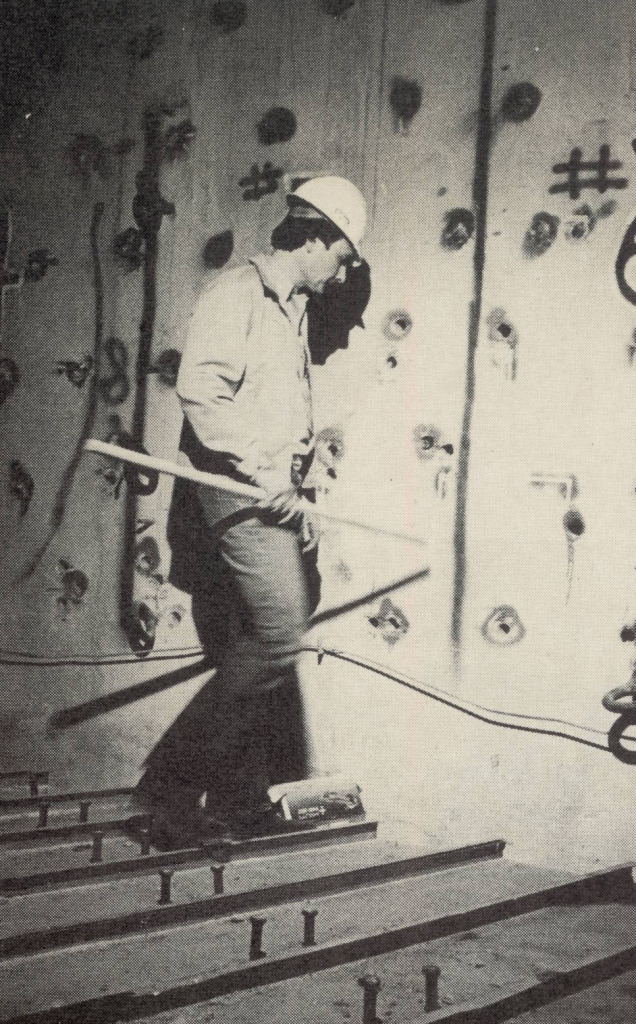
Picking up pieces at Matla
On August 27, 1980, the collapse of one flue in the triple flue chimney No 2 killed one worker and injured 15. The accident was indeed a freak by world standards and certainly unparalleled in South African construction history. The first phase of the investigation into the accident progressed and it was felt that the results should be made public on these findings. When the investigation began, removal of the rubble at the collapsed site was delayed because it was thought that its removal could prove dangerous for those workers involved in the operation. However, after extensive investigations and calculations, it was established that the rubble could be removed without serious risk to life and property. The only risk that did exist was that of falling bricks within the windshield. The steelwork had been designed for temporary erection at the top of the chimney. It was supported by the windshield and enabled moving platforms to be erected so that further examination of flues Nos. 4 and 5 could take place. A recheck of design calculations had indicated that the windshield i.e. the outer concrete surrounding the flue’s, was sound and that there was no danger of collapse of the remaining flues.
Some damage to the two other flues in the triple flue chimney had been reported, however but the damage was not seen as being too serious to allow repair. A design to further increase the stability of these two flues was own eating completion and repair work commenced.
The chimney was designed by Ove Arup and Partners
Stanton was originally called in after the collapse of the flue. At that stage no decision had been made regarding possible demolition of the chimney and the Manchester-based company was asked simply to remove the remains of Flue 6. Their wok was in fact, half complete when the decision was made to demolish the entire structure. Santon, in conjunction with American explosives expert Jim Redyke, then submitted a detailed proposal, which was accepted for demolishing the chimney using explosives
The blast due on July 18, has involved the drilling 1 000 holes – some 700 in the windshield itself and the remainder in Fule’s 4 and 5. The drilling, which was completed in eight weeks, took place at the 40m level where a slab has created a virtual “ground level” to distribute the mass and other forces through the base. All drilling was carried out internally. The remaining 40m will be demolished conventionally after the blast.
The success of the demolition will revolve around the hinge arrangement at the 40m level. The hinge was made up of vertical steel and concrete columns of differing lengths which forced the chimney, which was hoped to “walk”.
The demolition was fraught with problems, not least of which is the fact the Flues 4 & 5 were still standing within the windshield.
The two remaining flues naturally had a great deal of bearing on the direction of the fall. “If they start moving about inside the windshield as the chimney cmes down there could be major deviations in direction”.
To overcome this problem, horizontal wires had been fitted to fasten the flues back onto the wind shield.
Situated on top of the chimney were many tons of steelwork which originally formed part of Futurus’s internal hoists and once again this was tied by wires to the wind shield ensuring the minimum movement.
Basically, they were trying to keep everything as together as possible.
Blasting mats were to be fitted round half the circumference to prevent possible damage caused by flying concrete chunks.
The so called “target area”, lies between the coal staiths on one side and a cooling tower and the generator hall on the other.
Before the ballast Futurus had moved 50 000m³ of soil onto the site to create an impact cushion for the stack.
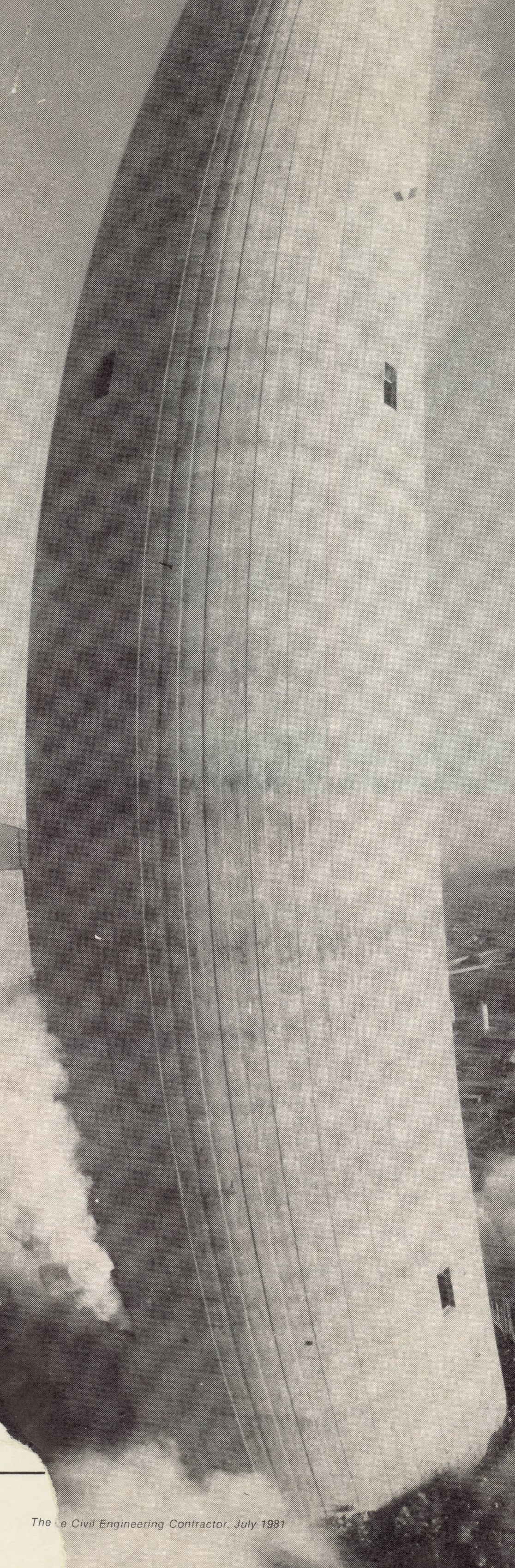
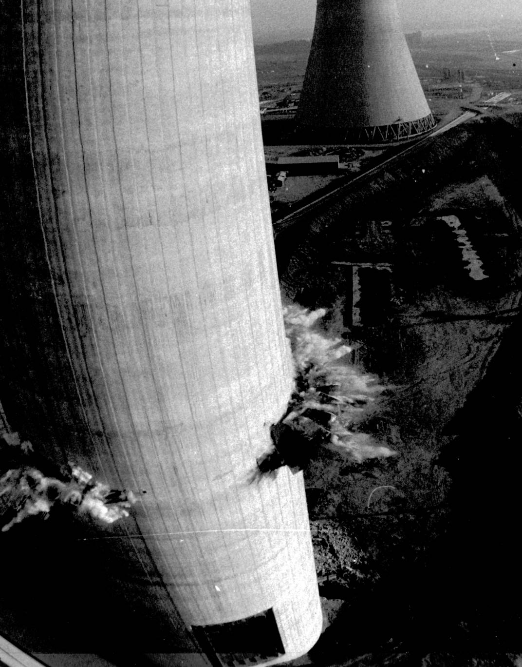
Sunday 19 July 1981
07:50 – A siren wailed in the bitter cold of the mid-winter morning warning us that the blast would take place in ten minutes.
07:55 – A voice, on the public address system, told us that the explosion was only five minutes away.
08:00 – An American Twang can be heard over the loudspeaker. “Ten, nine, eight, seven, six, five, four, three, two one … fire
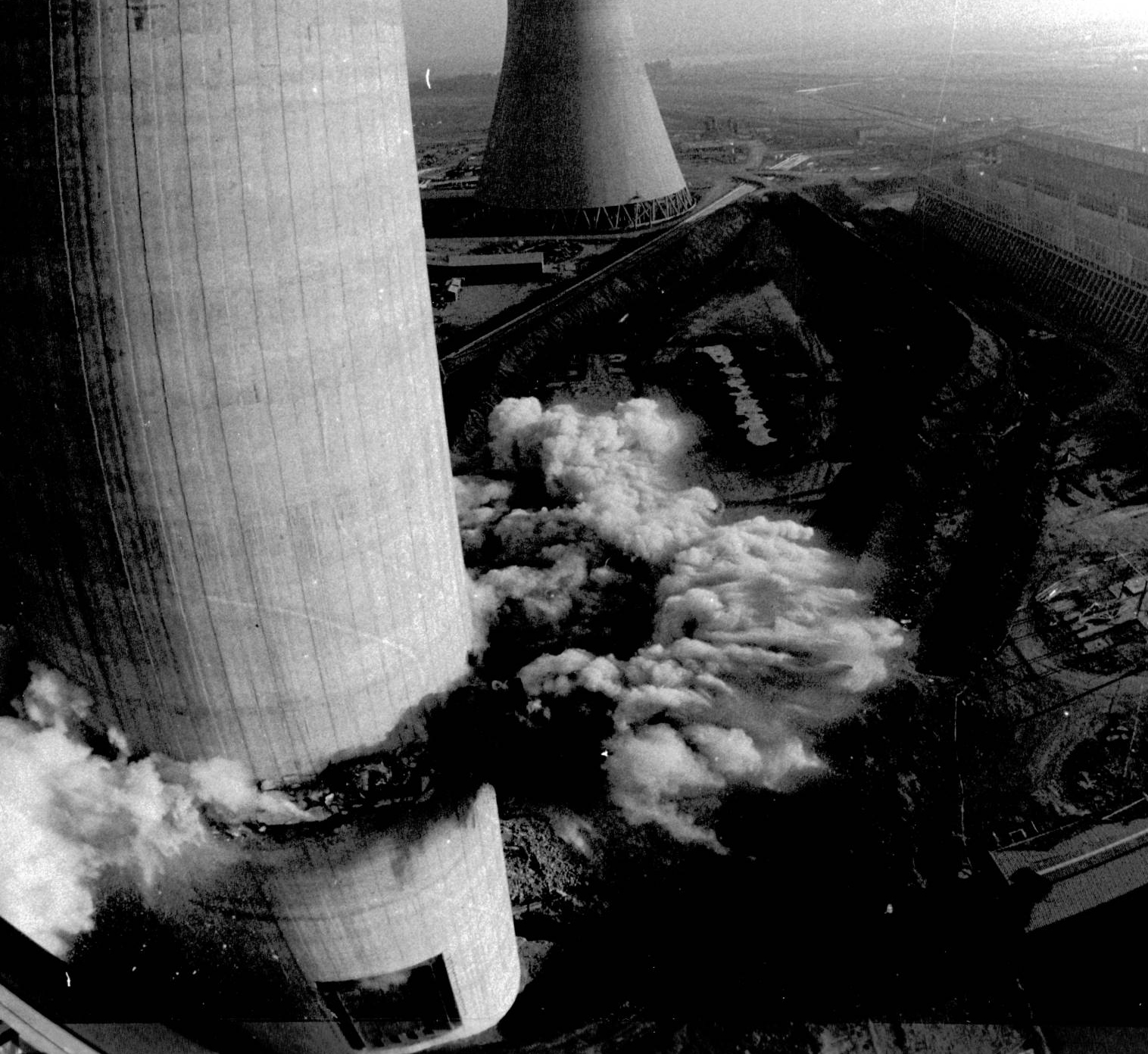
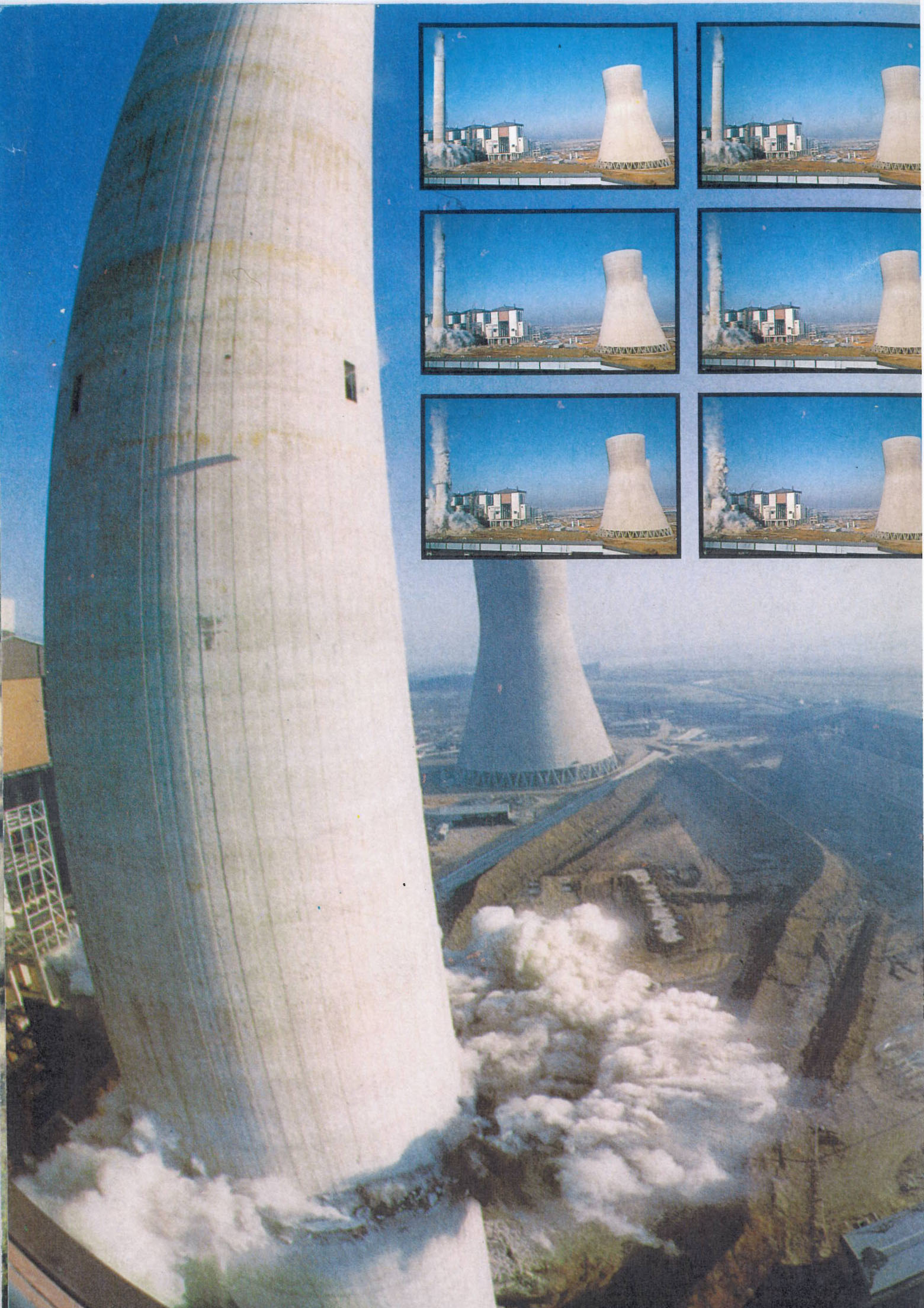
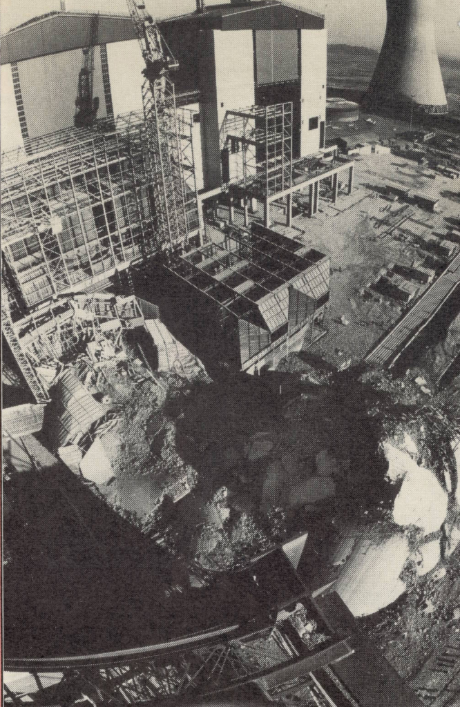
A red flare drifted lazily across the area and suddenly the steel plating across the tower erupted as the explosion smote the ear drums. Then it happened. Instead of falling like a tree the tower just crumpled seeming to crush itself as it came down. \immediate reactions were those of a total disaster, but nobody could say for sure until the massive 80m high dust cloud had settled.
As soon as was physically possible teams were sent in to assess the damage. They went on site about an hour after the blast. As they climbed the berm wall which had been constructed as part of the original plan they saw what looked like a comparatively small heap of rubble, rather less than one would have expected from such a massive structure.
Miraculously, all that had been damaged was the right hand section of the precipitator at Unit Five. This had been completely flattened and an ash line had been slightly fractured. They could not believe that it was physically possible to do that to that stack, said master blaster, Jim Redyke, afterwards. “In all my years and all my experience I have not seen anything like that – I just wouldn’t have believed it possible”.
ESCOM’s Chief Civil Engineer, added, “Initially when we decided to demolish the chimney we would have liked it to have fallen like it did but we took advice and everybody said that it couldn’t be done. The blast in fact took place as we would like it to have happened but certainly not as we planned it to happen”.
The controversial chimney stack had been beset with difficulties since the number six flue collapsed. The flue collapsed within the windshield leaving two portions intact.
- The spire, 54m high, being the back part of the bottom of the flue.
- 25m of the top of the flue which had come down through the 275m of the chimney with a clearance of 50mm on its circumference where it had passed through the middle slab of the stack.
The fall of the flue did not bring down the whole chimney, is itself a miracle. ESCOM was faced with the difficult decision whether to attempt repair to the collapsed flue or whether to
Contractor discussed preparations for the blast with Hi-tower on site a week before the event.
Hinges
In the original plan for the fall, the tower would have collapsed along a line which would miss the cooling tower and the coal staith. The direction of the fall was determined by two factors. First there was the axis about which the flues had to fall and secondly the ground area available. Had the stack fallen along the axis determined by the two standing flues it would have come too close to the coal staith for comfort. Thus it was necessary to shift the axis of fall 10º west of that direction in which the flues would tend to fall.
One of the measures undertaken to help ensure this, was the introduction of hinges to the inside of the chimney.
These hinges were placed at each side of the “smile” of bird’s mouth” blasting pattern at the tower’s 40m level. Four rolled steel joists were placed behind each end of the pattern and four were placed in stepped formation actually in the “bird’s mouth”. Weighing one ton and measuring six and a half metres each these were bolted on to the windshield and then encased in concrete. In addition, a concrete slab, 250mm thick, was cast at the 30m level. This was placed parallel to the hinge points and 90º to the direction of fall; it covered two thirds of the area of the stack. This was done to create a diaphragm and a measure of stiffness and it was intended that the hinges and the slab would absorb most of the downward fore of the stack during the blast.
“We introduced hinges into the structure, maybe the hinges failed we don’t know. Sand ESCOM’s Chief Civil Engineer.”
“But, said Redyke, every chimney we ever shot never had a hinge. We just allowed it to bear on its own mass. We added the hinges to increase the stability at the hinge point, to provide greater cross sectional hingery.”
Added to all the other imponderables it was felt that the construction of a hinge strong enough to carry the total load was impractical. The design time material requirements and construction time thereof would not be reasonable.
One of the biggest problems in preparing the chimney for the last was the stabilisation of the collapsed flue. Santon actually had to tie it to the wind shield with steel cables. The top of the 25m section of flue was resting against the wind shield while the bottom was resting on the mound of rubble. Any activity or work mound of rubble. Any activity or work carried out on it caused it to move and until it had been tied own it was extremely unstable.
It was further necessary to chip away what was left of the flue’s spire from the 54m level to the 40m level and to cut away some of the fallen flue. This was done so that access could be obtained to that part of the wind shield against which it was leaning. This access was required to admit personnel to drill the blast hoes to accept the dynamite charges.
Protection
In all, 7650 holes were drilled in a “smile”, or ”bird’s mouth” pattern into the wind shield. This was done at the 40m level around half the circumference of the tower. At widest the pattern was two and a half metres tapering to two thirds of a metre at the hinges.
In order to protect the cooling tower and coal staith a nine metre high berm was constructed in trough formation around what should have been the tower’s line of fall. Some 40 000m³ of earth were moved to build this Hi-tower called in Johannesburg-based earthmoving plant specialists.
Shock trenches, seven metres deep had to be dug to help absorb the impact of the fall. So successful were these that one of the seismographic instruments placed by ESCOM did not even record a reading.
A skirt of steel plating was placed around the wind shield to cover the blast holes at the 40m level. Santon also placed steel plating at the opening at the bottom of the tower. The intention of these was to prevent any material shooting out of the tower during the blast and damaging other structures. These were successful as we could not spot so much as a broken window after the blast.
Aftermath
We had all been very lucky. Granted; the blast did not go as planned. “The best laid plans of mice and men gang aft agly…” and this maxim seems to have plagued the Matla stack for a long while The construction of such a tower is a testament to man’s engineering ability, its destruction must cause sadness in the hearts of those who devoted their lives to building.