The Rationale Behind The Apollo-Cahora Bassa Scheme

THE RATIONALE BEHIND THE APOLLO CAHORA BASSA SCHEME
Where abundant water resources exist, hydro-electric schemes are the obvious choice for power generation projects, these being often the most economical way of providing electricity. Hydro-electric power on good sites are normally cheaper than that obtained from coal-fired power stations, which are prevalent in South Africa. The availability of cheap power stimulates industries, the development of towns and the creation of employment. At the time of the original undertaking in the early 1970’s, South Africa, as the most industralised country in Southern Africa, presented the only viable market capable of justifying the development of such a massive project. Hence co-operation between Mozambique, a country rich in water resources, and its drier but industrially more developed neighbour was seen as a way of providing economic and social benefits to both countries. At that time, ESCOM did not have a real need for the energy generated at Cahora Bassa, but by importing power it could obviate the need for building another coal-fired power station. This would not only save coal and reduce pollution, but also release the water supplies required by a coal-fired power station for other uses in South Africa. The agreement was that South Africa would pay a Reliability Premium to Mozambique, to be channelled into a fund aimed mainly at promoting agricultural development
Cahora Bassa and Apollo:
The Cahora Bassa project was initiated in 1969 when Portugal and South Africa signed contracts to finalize plans for the construction of the scheme. The construction contracts, signed with an international consortium called Zamco which comprises of 15 companies from Germany, Italy, France, Portugal, Switzerland and South Africa, provided for the following major infrastructure.
The 52 000 million cubic metre capacity Cahora Bassa dam on the Zambezi River 120 km up stream from Tete in Mozambique.
Two 1 414 km long 533kV high voltage direct current (HVDC) transmission lines positioned approximately one kilometre apart.
The Apollo converter station near Pretoria in South Africa which receives the 533kV DC, converts it back to AC and connects it to the country’s 275kV AC transmission network.. The first of the five 480 MVA generating sets at Cahora Bassa was commissioned in March 1975 and the first energy was transmitted from the power station to Apollo in May that year. The second third and fourth generating units came into operation respectively in July 1975, September 1976 and January 1977. The final unit was commissioned in June 1979. Contractual agreements made provision of the transmission of a firm 1450 MW to ESCOM.

TRANSMISSION OF POWER BETWEEN SONGO AND APOLLO
There are two options involving the two HCDV power lines between the Songo and Apollo converter stations.
The first which is the normal operating mode, entails the current flowing along one line and returning along the other line which, ensures that even if the line voltages are unequal there is minimal current (less than 30 Amps) returned via the earth path.
A significant element of the refurbishment of Cahora Bassa-Apollo link involved repairing the 900 km of double transmission like in Mozambique with many of the transmission line towers having to be rebuilt.
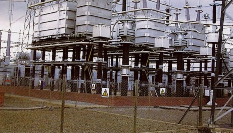
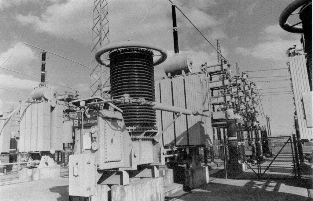
APOLLO CONVERTER STATION
Apollo substation is situated 20 km south of Pretoria at an altitude of 1 510 m. It is a strong nodal point in Eskom’s 400 and 275 kV national grid and also houses the Apollo converter station which is the receiving terminal in the Cahora Bassa/Apollo High-Voltage Direct Current (HVDC) scheme.
The Scheme was conceived in the sixties to export hydro-electric energy generated at the Cahora Bassa Dam in Mozambique to South Africa to finance agricultural mining and industrial development in the potentially rich Mocambican province of Tete.
As the first HVDC scheme committed to thyristor technology, it marks an important step in the development of power electronics.
Contractual work and financing were undertaken by an international consortium of 15 companies from West Germany, Italy, France, Portugal, Switzerland and South Africa. The third and final stage of the project was completed at the end of 1979
Filtering Out Harmonics
The inversion of the incoming DC to achieve AC does not immediately provide idealised smooth sinusoidal wave forms and it is necessary to reduce the effects of and filter out harmonics. In order to reduce the effects of harmonics when the arriving DC voltage is inverted o AC, the converter bridges are paired with 30 degree phase-shifted transformers. In addition two sets of harmonic filters are used to eliminate harmonics in the current at both Apollo and Songo terminals. These filters are tuned to eliminate, 5th, 7th 11th, 13th and high order harmonics. A third AC harmonic filter which is tuned to eliminate 11th, 13th, and high order harmonics provides a back-up at the Apollo terminal. The filter banks also produce 400 MVAr of reactive power at 50 Hz required by the converters for power factor correction. The two capacitor banks at Apollo provide the rest of the reactive power required by the converters.
To reduce interference in the public telephone system, DC line filters tuned to 300 Hz, 600 Hz 900 Hz and 1 200 Hz, filter out the 6th, 12th, 18th and 24th orders of Dc harmonica generated by the converters.

The Control and Protection System
A grid master power control system (GMPC) co-ordinates generation, high voltage DC and AC transmission and enhances frequency control Cahora Bassa. The GMC is able to exploit the fast reaction of the high voltage DC system to follow variations in generation and AC transmission. The control protection and voice communication channels between Songo and Apollo are provided by duplicate power line carriers coupled between the main conductors and insulated shield wires. The system at both converter stations has been replaced as part of the refurbishment work and a repeater station located in South Africa 300 km from Apollo is used to relay the power line carrier transmissions. A similar repeater station in Mozambique was decommissioned.
The refurbishment work undertaken to rehabilitate the Cahora Bassa- Apollo link also involved replacing the DC control system at the Apollo and Songo converter station with a new state of the art system. This included replacing the man machine interface (MMI) for operations and switching.
The Songo converter station usually controls the DC current, while Apollo determines the voltage on the lines. Should Songo have insufficient voltage, these control modes are reversed to prevent a breakdown in the transmission of power. The GMPC Songo to Harare following the completion of the 400kV AC inter-connector to Dema.
The turbines at Cahora Bassa are protected by a temporary 10% pole current overload which mitigates turbine over speeding.
Converters
The eight six-pulse thyristor bridges can function in both the rectifier and inverter modes. The system control are designed in principle to allow also for power flow back to Cahora Bassa to cater for possible future requirements
The bridges are arranged in two poles of four around the earth electrode connection. Twelve-pulse effect for harmonic reduction is achieved by operating converters with 30° phase-shifted transformers, in pairs. Each bridge, rated at 133kV DC and 1 800 A (240 MW) is provided with the necessary switching equipment for polarity reversal and for its insertion into the series DC circuit – the main principle being that the DC current cannot be interrupted with impunity.
Two parallel thyistors are required for the 1 800 A rating. The first stage equipment employs 280 thyristor pairs in series per valve. The later stages, which have the advantage of an improved thryistor, require only 192 pairs.
The eight bridges at Apollo contain a total of 22 656 thyristors. The 10% built-in redundancy can be monitored only in the off state.


A unique feature of this pioneering scheme is the use of oil-cooled and oil-insulated thyistors housed in outdoor valve tanks on insulated platforms. The use of these platforms makes the valve tanks, unlike the transformers, completely interchangeable. A special lifting vehicle, the Lifting Platform Hauler (LPH), installs and transports the elevated valve tanks, the damping circuit tanks, the transformers and the DC reactors within the station.
The restricted short-circuit-current withstand capability of the thyristors available at the time of design necessitated the installation of unconventional fast-acting short-circuiting switches (Overcurrent Diverters) for valve protection. As a direct consequence, the transformer had to be made short-circuit proof.
An inductive loop firing system operating with energy supplied from ground level provides the necessary triggering pulses for the thyristor pairs. Fibre optic light beam transmitters provide the isolation for the control impulses at ground level.
Auxiliaries
Two motor-generator sets with fly-wheel energy storage provide the essential power at 75 Hz for thyristor firing, control and protection.
Non-evaporative forced-air-cooled heat exchangers provide the cooling for the thyristor valve oil. At high ambient temperatures, spray water can be introduced for additional cooling effect.
The thyristor technology development itself provides valuable spin-off advantages for other power electronic systems, such as static compensators, variable speed and battery storage plants.
The Cahora Bassa/Apollo HVDC Scheme has without doubt triggered an avalanche of technological development. Once the circumstances are more favourable it can also make significant contributions to the socio-political, agricultural, industrial and mining development in the southern African Continent
Clearing Faults
Transient faults on the DC lines are cleared by up to four full-voltage re-energising attempts, each subsequent attempt preceded by increasing times allocated for de-ionisation. The second attempt to clear the fault is usually made with the lone voltage having been reduced by that of one converter bridge. Line faults are detected by a travelling wave system with backup provided by a slower differential current measurement.
Operating the Apollo Converter Station
Altoget
her, 31 people handle operations, maintenane and technical support at the Apollo converter station. The Apollo Governance Team, which is represented by the leaders of it Electronic Maintenance, Electrical and Mechanical Maintenance, Operations and Technical Support teams oversees the running of the HVDC terminal.
This team deals with all financial, technical engeineering an human resource issues and it is responsible for all major deisionsd affecting plant. When required, specialists, stakeholders and customers join the team as ad hoc members. This team approach embraves the process organisation of Transmission and continues to add value.
This team deals with all financial, technical engineering and human resource issues and it is responsible for all major decisions affecting plant. When required, specialists, stakeholders and customers join the team as ad hoc members. This team approach embraces the process organisation of Transmission and continues to add value.
Operation
Hydro
-electric AC power generated at Cahora Bassa’s South Bank power station by five 480 MVA machines is transmitted at 220 kV to the Songo rectifier station 6 km away. Here 1920 MW is converted to +533 kV and -533 kV DC at 1800A and transmitted 1414 km over two monopolar lines to Apollo. With transmission losses amounting to approximately 120 MW, 1 800 MW arrives at Apollo for conversion to 275 kV AC. Three Ac harmonic filters and two shunt capacitor banks at 275 kV provide 1 100 Mvar for power factor correction.
Conclusion
As the first major HVDC scheme which was fully committed to the then novel thyristor technology, Cahora Bassa/Apollo marks the historical turning point from mercury-arc HVDC valves.
The scheme contains many unique features which however, have not been carried forward into more recent schemes because of the rapid technological advances made in the HVDC field. These include:
- Outdoor oil-cooled oil-insulated valves
- Overcurrent diverters
- Short circuit proof transformers
- Magnetically triggered thyristors
- Valve auxiliary energy from ground level
- Monopolar transmission lines
- Continuously rated earth electrodes

CAHORA BASSA PROJECT

In 1969 contract were singed in Lisbon between the State of Portugal and the Government of the Republic of South Africa to finalise plans f. At the same time, construction contracts were signed with Zamco, an international consotrium, constituted by 15 member companies from West Germany, France, Italy, Portugal and South Africa. The contracts provided for the construction of a dam at Cahora Bassa in Mocambique, and underground power station on the south bank of the Zambezi River, terminal converter stations at Cahora Bassa and at the Apollo substation near Pretoria in South and double direct current transmission lines over 1 400 km between Cahora Bassa and Apollo.
The project was one of the most exciting of the century.
Eskom is a recognized world leader in the field of high-voltage transmission at high altitudes over long distances. At this stage, however, it was not the technological expertise which was a major consideration in the scheme.

As the most advanced country in southern Africa, South Africa was the only viable market which could justify the development of such a massive project as that envisioned at Cahora Bassa, Mocambique and its neighboring countries were not sufficiently industrialized to utilize the amount of energy generated by the proposed hydro-electric scheme.
Eskom did not at the tie have a real need for energy generated at Cahora Bassa, yet by importing power it did stand to gain some advantages. For instance, importing power could obviate the necessity of building an additional coal-fired power station. This would not only save coal resources, but also release internal water supplies for other industrial, commercial or domestic use.
In addition, South Africa already boasted Eskom’s national power network, linked to Lesotho, Botswana, Swaziland, Nambia and Mocambique. Energy fed from Cahora Bassa into the power grid could then be distributed to any point of demand along that network.
As the result of discussions held in 1984, contracts concerning Cahora Bassa were renegotiated to include the now independent Peoples Republic of Mocambique.
The original vision was reconfirmed and strengthened – and with it a new concept, ENGINEERING FOR PEACE.
The geographical framework
The area generally referred to as southern Africa includes Botswana, Swaziland, Lesotho, Malawi, Zambia, Zimbabwe, Namiba, Mocambique and South Africa. All these countries are rich in natural resources, from water supplies and fertile land to minerals. Resources however, are of no use until they are developed and unless there is a market for them. Two of the main problems confronting most southern African countries are the lack of established infrastructures and the lack of markets to justify development of their resources. Only South Africa, with its rapidly developing industrial and commercial sectors, could provide the immediate market which these countries needed, In addition, South Africa possesses and established and rapidly developing infrastructure. It has a sophisticated First world economy set in a Third World region and is consequently admirably situated, economically and industrially, to boost the economies of the neighbouring countries.

The irony of this situation was that all these countries provided the South African labour market with unskilled labour whose earning in many cases significantly contributed to their country’s economy. It would seem a natural step to sell something more lucrative than unskilled labour – namely water and power.
Hydro-electric power and Mocambique
Where there are abundant water supplies, hydro-electric power is the obvious choice for the development of power generation projects since it is the most economical form of electricity. Cooperation between a country rich in water resources like Mocambique, with its dryer but industrially developed neighbor in establishing a grid of water and electricity networks would provide economic and social benefits for both, stimulating local industrial development and increasing export possibilities.
Mocambique is a Third World country rich in natural resources, but lacking an efficient infrastructure. The potential for agricultural development is vast – the land is fertile and capable of high production of tea, sugar cane, rice nuts, vegetables, citrus and subtropical fruit. It has vast and practically undeveloped fishing and mineral resources. The potential for the tourist industry includes coastal waters, gam reserves and the scenic interior. Three harbours, Beira, Maputo and Ncala, could handle considerable quantities of trade. The Zambezi River has almost untapped potential for the development of hydro-electric power, which started with the Cahora Bassa Dam project.
The purpose of the project was to export power initially to South Africa which would give a surplus royalty to Mocambique to be channeled into a development fund. The fund would be utilsed mainly to promote agricultural development.
Advantages of the Cahora Bassa project

Irrigation schemes would encourage agricultural projects, forestry and fishing industries which in turn would raise the standard of living. Improved water supplies for riparian villages and settlements would also raise the general standard of health as well as encourage stock breeding.
The dam regulates the flow of the river, lessening the consequences of drought and dramatically reducing the dangers and damage caused by flooding –common events in this part of the world. The improved irrigation would enable farmers to introduce more efficient and scientific farming methods. Small-related industries are encouraged, such as food processing and canning.
Hydro-electric power is generated more economically than that supplied by coal fired power stations. The availability of power at low cost triggers an upsurge in the growth of light and medium industries. Towns began to develop, employment opportunities profilerate and with them, improved training and education facilities. Entrepreneurship is stimulated. As new areas open up for development of local resources, communication is improved and the general infrastructure developed.
Economic and industrial development encouraged political and social stability. Economic and technological interdependence and joint participation in industrial and commercial projects foster cooperation between countries.
The status of the project

On 25 March 1975, the first generating set was commissioned. The first transmission of energy from the power station on the south bank to the Apollo substation in South Africa took place on 19 May 1975. The second generating unit came into operation 3 July 1975 and he the third and fourth on 17 September 1976 and 25 January 1977 respectively. The final unit was commissioned on 22 June 1979.
Total capacity of the five units is 2000 MW at 16 kV. This is about half the generating capacity of one of the six-unit coal-fired “giants” Eskom is currently building in South Africa, which generates up to 3 6000 MW.
A second power station was scheduled for construction on the north bank at Cahora Bassa with four 400 MW generating sets.
Contractual agreement made provision for the transmission of 1750 MW to Eskom. The potential for energy supply to Malawi, Zimbabwe was as yet untapped, though further projects were technically and economically viable.
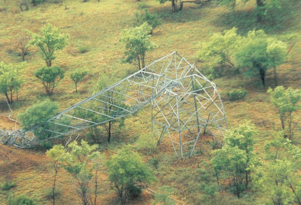
Civil war in Mocambique disrupted the original construction and commission schedules and has since extensively damaged power lines and towers. This has effectively hindered commercial, agricultural and industrial development of the area and to all intents and purposes significantly delayed the eventual growth of a South African grid
Surveys of damage
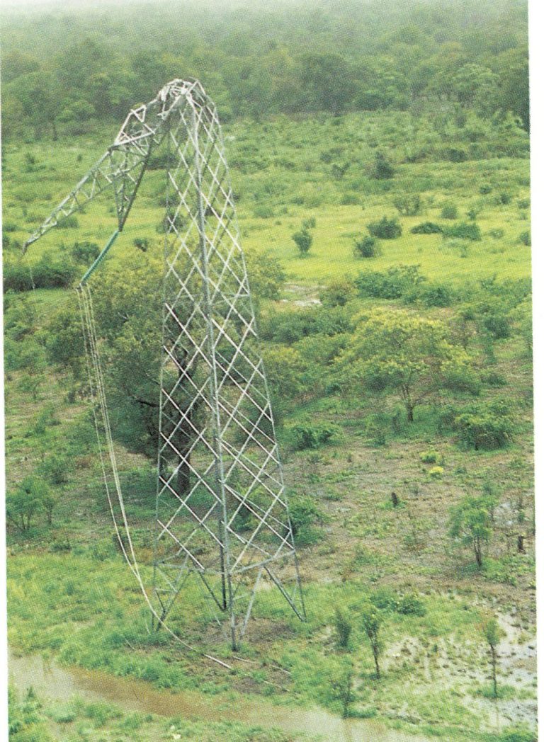
Phase conductors would have to be totally replaced. On-site inspection in areas concerned would be necessary to determine how much of the earth conductor can be reused, since it has not been damaged to the same extent. However, if the urgency of the repair work was to take priority then it would have been preferred to replace the earth conductor to avoid the time-consuming task of jointing.
It is estimated that approximately 20% of the insulator discs could be reused. On-site inspection will, however, verify whether mechanical failure would lead to rejecting a higher number of discs.
At least 80% of the space-dampers were replaced or repaired. Servitudes and access routes needed maintenance.
Recommended construction programme
Initial negotiations with contractors concerning repair work indicated that at least one of the lines could be repaired and put into operation during the dry season of 1988. Repair of the second line was undertaken shortly afterwards.
The costs estimated for the work were $30,2 of which about two thirds were required to repair damaged transmission lines and a third to rehabilitate the remaining lines in Mocambique.
International cooperation
Taking their cue from the functional and successful Beira/Mutare oil pipeline, Portugal, Mocambique and South Africa had recently set up plans to provide protection for the Cahora Bassa transmission lines. It was intended to establish a “third-party” company which would act as a distribution entity between Hidroélectrica de Cahora Bassa (HCB) – the Mocambique Company operating the Cahora Bassa dam and power station – and Eskom in South Africa.
The revenue will be used to enable Portugal to repay loans negotiated for the construction of the Cahora Bassa Project and secondly to provide Mocambique with funds for agricultural and industrial projects planned for the region.
Once the scheme was fully operational, Mocambique would decide on the construction of the planned north-bank power station.
He vision for the development of a southern African grid would be a step closer. The creation of greater political stability, social and industrial development and improved standards of living for all southern African populations would be fostered by international cooperation. We would see the realization of a long-nurtured aspiration.
CAHORA BASSA AN AFRICAN SOLUTION TO AN AFRICAN CHALLENGE
For the first time in Africa in November of 1994, the ICOLD (International Commission on Large Dams) held its 8th congress in Durban, which was a major event which was only held in the great cities of the world like Paris, New York, Stockholm, Vienna, New Delhi, Mexico City, Washington, Istanbul, Montreal, and San Francisco, to name but a few. So this was a major coup for Southern Africa.
To traders and explorers of old in Africa the place was known as Kebra Bassa – the work is done – for it was here where rapids ended the river journey by small boats from the coast and bearers waited to ferry goods further inland. Kebra Bassa was a short distance upstream on the Zambese River from the river bank village of Tete, established in 1545.
The African explorer David Livingstone who passed through in 1858, was but one of many famous personalities to visit Tete.
century later, in 1959 Portugese engineers and surveyors arrived to identify Cabora Bassa – a steep narrow gorge about 500 km from Kariba and the same distance from the sea – as the ideal site for one of the most exciting hydro-electric projects of the century. Following an extensive
Zambese valley development survey, work on the Cabora Bassa scheme commenced in 1968. The Portuguese were strongly backed by by Dr van Eck, a pioneering South African business leader and Dr R L Straszacker, the then Chairman of ESCOM.
It was during the early stages of construction that much was gained from the experience of one of the world’s greatest dam builders, Dr Henry Olivier. To him Cahora Bassa was a vital link in an energy chain that would open up the resources of Southern Africa for development to their full potential.
What had been created was an inland lake 270 km long and at places 30 km wide, covering 2 660 square kilometres. It provided the water energy for the 2 000 MW underground hydroelectric power station.
The Cahora Bassa Apollo High Voltage Direct Current (HVDC) scheme transmitted the largest amount of power at the highest transmission voltage over the longest distance in the world, using the thyristor technique.
It was a magnificent achievement of international co-operation by the South African-led Zamco consortium that brought the vision of the development of a Southern African power grid a step closer.
The vision to transform the sub-continent and open unimaginable vistas of growth and development was, however, short lived.
Southern Africa was almost back to 1906 when the founders of the Victoria Falls Power Company dreamt of harnessing the power of the Zambese River to feed the growing power demands of Johannesburg and the Reef but lacked today’s long-distance transmission technology. Cahora Bassa became a slumbering African giant, waiting now for nearly 20 years for the day that it may yet fulfill its destiny: to unlock the door through which energy will flow, bringing new development and hope to millions of people in Southern Africa.
Hydro-electric AC power generated at Cahora Bassa’s south bank power station by five 480 MVA machines is transmitted at 220 kV AC to the Songo rectifier station 6 km away. Here the AC voltage is converted to plus/minus 533 kV DC. 1 920 MW is transmitted 1 414 km over two monopolar lines to the Apollo inverter station in South Africa. The imported power is reduced to 1 800 MW through transmission losses amounting to 60 MW per line and conversion process.
Transmission modes
The three modes are:
- The normal bipolar mode with opposite polarity line voltages ad balanced line currents ensuring minimum ground return current (adjusted to about 20 A anodic for electrolytic corrosion prevention) even with unequal line voltages.
- The 50% power
- When one line or pole is unavailable, 50 % power can still be transmitted using the other line and pole (monopolar mode) while the full 1 800 A line current is returned via the earth electrodes.
- An emergency or parallel operation mode permits the transmission of 80% power over one line employing the converter poles in parallel. During this mode the line is operated at its maximum thermal rating of 3 300 A which is also the rating of the earth electrodes.
Dam Wall
- Type Double curved concrete arch
- Max height above foundations 171 m
- Max width of foundation 21,5 m
- Crown length 303 m
- Dam crest altitude 331 m
- Storage level (maximum flood) 326 m
- Maximum drawdown level 275 m
- Total discharge capacity 13 200 m³/sec
- Volume of concrete 450 000 m³
- Excavation for foundation 210 000 m³
Flood control
- Segmental gates 8 x 1 650 m³/sec
- Crest spillway 350 m³/sec
- Total 13 550 m³/sec
Dam
- Length 270 km
- Breadth 30 km
- Depth 140 m
- Capacity 52 000-million m³
- Low water inflow 1 000 m³/sec
- Average water inflow 2 800 m³/sec
- Maximum flood inflow 17 700 m³/sec
- Surface area 2 600 km²
- Dam catchment area 900 000 km²
- Total river catchment area 1 240 000 km²
Power Station
- Generating units 5
- Penstocks 5
- Tailrace tunnels 2
- Surge Vessels 2
Turbines
- Type Francis Vertical
- Output 415 MW
- ±Speed 107,1 r/min
- Effective Head 103,5 m
- Consumption 452 m³/sec
- Penstock length 170m – dia. 9,7m
Generators
- 480 MVA – Power Factor 0,85 50 Hz
- 16 kV ± 5% 56 pole
- Xd = 14,5% 107,1 r/min
- Static excitation through thyristors
- Rotor diameter 13m
- Rotor mass 950 tons
- Flywheel effect 115 000 tm³
- Auxiliary generator 5 MVA, 6,6 kV, PF 0,8
- The generators are connected to transformer banks housed in a cavern by isolated phase busbars with a current-carrying capacity of 18 000 A.
Generator Transformers
- Yd connection Single phase units – 160 MVA units
- Impedance 9 – 11%
- Mass without oil 130 tons
AC Auxiliary power supplies
- Cahora Bassa 1 MVA, 20kV diesel generators ongo
- Main AC supply 2 x 20 MVA, 220/20kV transformers
- Emergency supply 3 x 4 MVA/6,6 kV diesel generator
- DC supplies Various dual battery sets
- Secure electronic supply 3 motor generator sets with flywheels each
- 100 kVA + 500 kVA/ 380V at 75 Hz
- Apollo: Main AC supply 3 x 20 MVA, 22/11 kV transformers fed from tertiaries of 400/275 kV coupling transformers
- DC supplies Various dual battery sets
- Secure electronic supply 3 x motor generator sets with flywheels, each 100 kVA + 500 kVA/380 V at 75 Hz
Converter station equipment
- AC Switchgear Songo Apollo
- Voltage 220 kV 275 kV
- Type Air blast Air blast
- Breaking capacity 24 GVA 15 GVA
- Basic insulation level 900 kV 1 130 kV
AC filter circuits
- Tuned banks for 5th, 7th, 11th, 13th harmonics and high pass filters for higher orders
- Capacitors Mixed dielectric, externally fused, PCB impregnant (no longer PCB)
- Reactors Oiled-cooled, air-core with tap changer
- Frequency range 49,2 Hz to 60,6 Hz
- 49,55 Hz to 50,45 Hz normal
- 49,40 Hz to 40,55 Hz and 50,45 Hz to
- 50,6 Hz for 20 seconds
- Shunt reactive
- Power at 50 Hz: Songo 200 to
- 400 Mvar
- Apollo 1 100 Mvar in 5 stages
- The filters, which are disconnected immediately below 49,4 Hz and above 50,6 Hz, limit the residue of harmonic voltages to below 3% and the individual harmonic voltages to below 1,5% of the fundamental.
Converter transformers
- Single phase units; Yy0 for bridges 1,2,5 and 6
- Yd5 for bridges 3,4,7 and 8
- Neutral end 27 position tap changer
- The 30º vector displacement facilities 12 pulse bridge operation effectively cancelling the 5th and 7th harmonics entering the AC system under balanced conditions.
Details of single phase units
- Songo Apollo
- Size 96,7 MVA 90,8 MVA
- AC winding 133 kV ± 16% 186 kV ± 16 %
- In 13 steps in 13 steps
- DC winding 114 kV 04 67 kV 107 kV or 62 kV
- Impedance 16% 16%
- Taps ±13 steps ± 13 steps
- Insulation of AC winding and bushings graded to suit series potential of bridges. Mass of largest units (for Bridges 7 & 8): 163 tons without oil.
Converter Bridges
- Bridge details 240 MW, 133,3 kV, 1800 A, two valve arms in common bell tank, three bell tanks per bridge
Valve cooling oil circuit:
- Songo One oil/water heat exchanger per bridge plus
- two wet cooling towers for the station.
- Apollo Dry cooled (spray assisted for hot ambient
- conditions), 4 pumps and 6 fans per bridge
Stage 1 Stage 2 and 3
- (bridges 1,2,3,4) (bridges 5,6,7,8)ristors
- Thyristors 1 650 V, 900A 2 400 V, 900A
- Valve arm 280 pairs 192 pairs
- Total numbers of Thyristors for the Scheme: 45 312
Valve RC dampers
- Two units in common oil tank
- Capacitance 20 nF
- Resistance 3,5 k?
- Total mass (2 units) 20 tons
- Smoothing reactor
- One for each pole on line end 0,83 H, 1800 A,BIL 1 725 kV
- Dimensions Length 7,4 m
- Height 4,3 m (exc. Bushings)
- Width 3,7 m
- Mass with oil 200 tons
- Mass without oil 175 tons
DC line surge capacitors
- Capacitance 0,1 uF
- (forms part of DC filter for 300, 600, 900 and 1 200 Hz)
Thyristor protection
- Overcurrent 3,5 x 1,8 kA use thyristor control
- Overcurrent 3,5 x 1,8 kA use overcurrent diverter to commutate current away from valve (having a
- making capability of 25 kA, a short time rating of 10 kA and a closing time of 4 ms)
- Overvoltage by a combination of surge arresters on the line, bridge platforms to earth and across and AC and DC bridge connections.
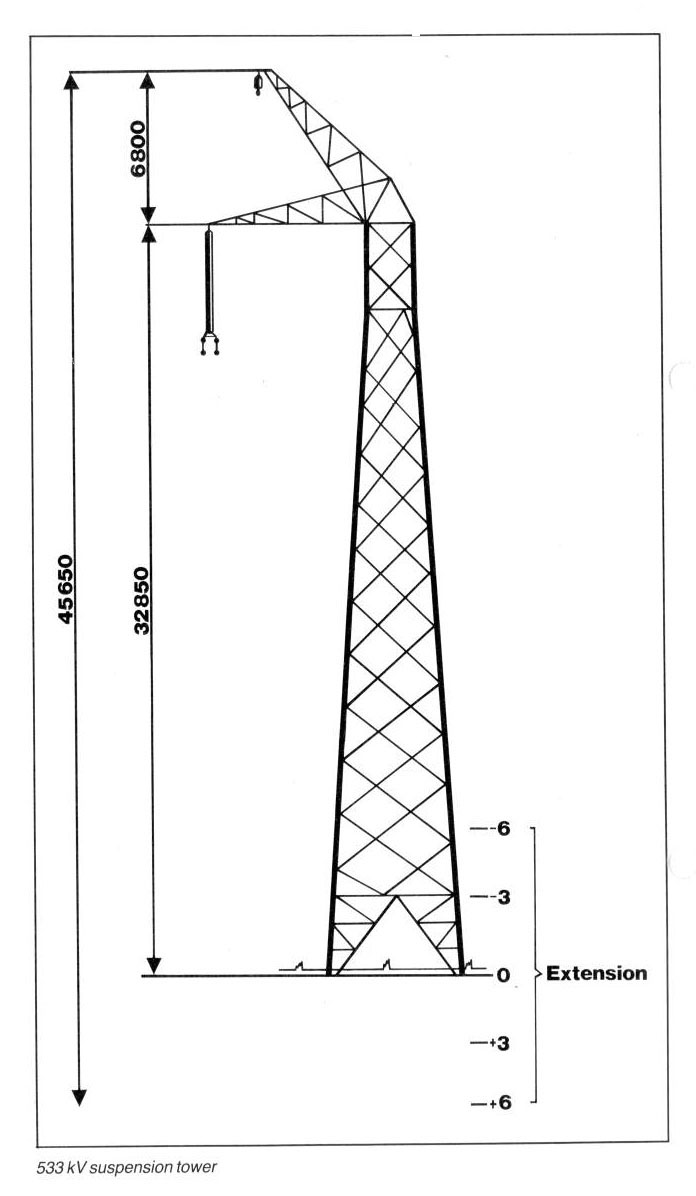
HVDC monopolar transmission lines
- Number 2 (1 to 2 km apart)
- Route distance 1 414 km
- Number of towers 7 000 (approx.)
- Ruling span 425 m
- Maximum span using Reinforced towers 700 m
- ± 3 and 6 m Earth wire Single SCA, Cu equivalent 73,5 m
- m² 12 x 3,52 mm A1 + 7x 3,52 steel, “Oden”
- Protection angle 15°
- Toughened glass anti-fog Insulators 320 mm dia., 510 mm SCD
- Phase configuration Quad conductors 45 cm apart
- Conductor SCA, Cu equivalent 342 mm²
- 42 x 4,13 mm A1 + 7x 2,32 mm steel, “Zambezi”
Clearances:
- Live metal to earth 3,65 m live metal to earth (swing conditions) 3,3 m
- Conductors to ground 8,55 m
- Conductors above roads 12 m
- Conductors above railway 14,5 m
- Line fault protection Instantaneous travelling wave
- Time delayed differential current
Earth electrodes
- Songo Estima 2 x 20 km lines,
- 5 deep electrodes
- 3 300 A
- Apollo Zwavelpoort 1 x 14 km line
- 5 deep electrodes
- 3 300 A
Telecommunications
Dual power line carrier system transmitted on insulated earth wire and main conductors. Relay stations at Pietersburg and Vila Cantandica, 300 km from each end?