Tutuka Power Station
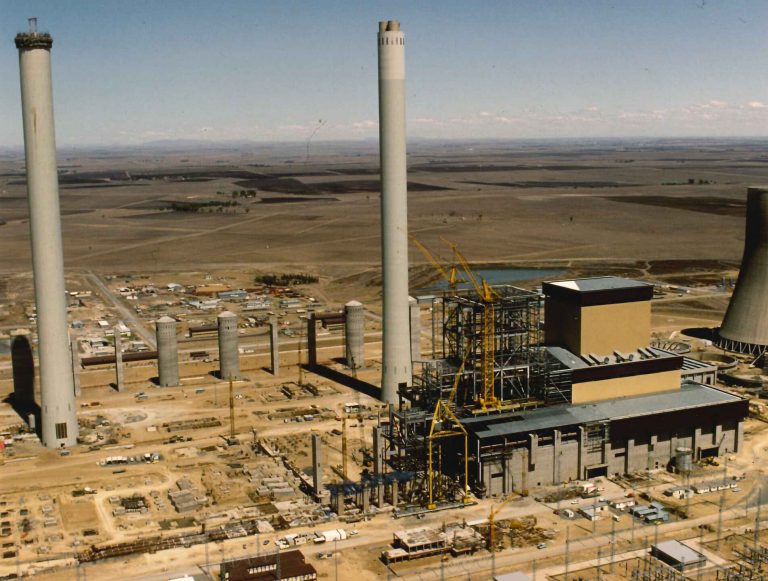
Tutuka is the Zulu word for progress. The construction of Tutuka began in October 1980. The first unit was commissioned in March 1985 and the power station was fully commercial by June 1991.
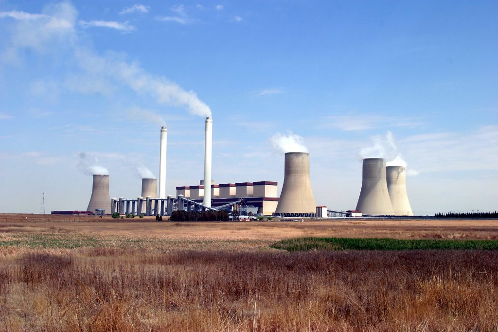
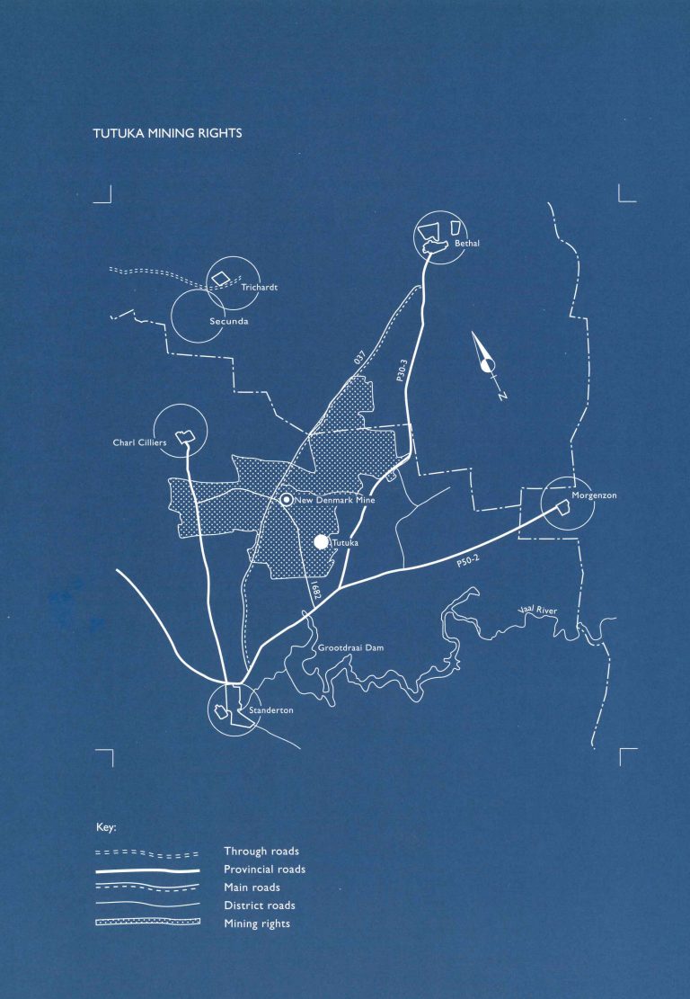
Tutuka is situated 25 km from Standerton in Mpumalanga, was the first power station to feed energy into Eskom’s 765 kV extra high voltage system. The coal-fired, six boiler/turbine unit giant contributes 3 600 MW supplied to consumers and industries throughout the country.
Electricity is distributed via the substation Alpha where the voltage is stepped up to 765 kV. Substation Alpha links Tutuka’s 3 600 MV via short transmnission lines with the 765 kV grid. Tutuka was completed on 3 June 1996.
Tutuka was the first power station to feed energy into Eskom’s new 767 kV extra-high-voltage system. The 765 k power lines were strung from 45 metre-high pylons spaced along an 80 metre servitude.
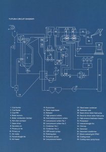
The basic cycle
Conveyor belts transport the coal from the stockyard via silos to the boiler bunker into the furnace where it burns at a temperature of approximately 1 500ºC. Dust and ash are produced as a result of combustion in a ratio of 10.1. The ash falls to the bottom of the boiler and into a submerged scraper conveyor trough where the dust is separated from the flue gases in electrostatic precipitators, cleaner flue gasses pass through the chimney into the atmosphere 275m above ground level.
Heat produced by burning coal is absorbed by the boiler feed-water in the 500 km of tubing that forms the boiler walls. The water is converted to steam at high temperature and pressure is passed through super heaters to the high-pressure turbines.
Spent steam is condensed and pumped via feed-heaters and de-aerator to boiler feed-pumps and then back to the boiler to repeat cycle. The condenser contains more than 22 500 tubes. The cooling water is itself sprayed into the lower levels of a cooling tower where evaporation removes the unwanted heat from it. The up-draught in the cooling tower is due entirely to convection.
Coupled to the shaft of the four in-line turbines is the generator rotor, which is a cylindrical electro magnet, enclosed in a gas-tight housing. The electricity passes from the generator stator windings to a transformer, which raises the voltage from 22 kV to the national voltage of 400 kV. The electricity is distributed via substation Alpha, where the voltage is stepped up to 765 kV.
Substation Alpha links the 3 600 MW Tutuka power station via short 400 kV transmission lines with the 765 kV transmission grid. The 400/765 kV transformers are each rated at 2 000 MVA and the 765 kV reactors are each rated at 400 MVA. The 400 kV switchyard is of conventional outdoor construction utilizing strung conductors and having a load current capacity of 3 150 A and a short circuit current level of 50kA.
The Plant
Control
Each of Tutuka’s six boiler-turbine sets is run as a separate entity with its own controls and instrumentation incorporated in its own control desk and panels. There are three control rooms, each serving a pair of sets. Operators monitor and control the computerized functions associated with start-up normal operation, shut-down and emergency operation. The operators are in permanent contact via the station control room with other Eskom control centres that make up the integrated transmission network.
Data-logging computers continuously monitor the main operating and alarm systems and provide a constant flow of information on video screens and printers.
Fuel handling
Coal crushed smaller than 25 mm is delivered by belt conveyor from the New Denmark Colliery and stored in the local stockyard. The coal is conveyed to the storage areas and recovered by one of three stacker re-claimers, or is fed directly to the power station. Total storage capacity of the stockyard is 3 million tons and coal can be transferred to the power station at rates of up to 2 500 tons per hour. At the power station, coal is stored in six 4 500 ton capacity silos, each of which can serve two boilers. From the silos, belt conveyors transfer the coal to 675 ton capacity boiler bunkers, of which there are six per boiler giving an effective storage capacity at the boilers of 12 hours’ operation at full load. When a furnace is started up, fuel oil is used until the combustion of the pulverized coal is stable. A Tutuka four storage tanks with a combined capacity of 4 800 tons are used for fuel oil.
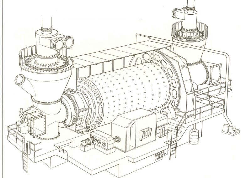
Mills
Coal from the boiler bunkers is fed under control into the mills. The feed rate is determined by the steam requirements. Inside the rotating tube mills, steel balls pulverize the coal. The fine, highly combustible powder is blown from each mill into the boilers at approximately 50 tons an hour. There are six mills to each boiler, providing a spare capacity of one mill per boiler when coal of design quality is being burned. At full capacity each boiler required between 235 and 310 tons of coal an hour, depending on the calorific value of the coal.
Boilers
The six Benson-type boilers depend on forced circulation under start-up conditions and include no steam drum. The highly purified and de-mineralized feed water flows in a continuous circuit through boiler, turbines condenser and back to boiler. As it passes through the boiler, the feed water evaporates and the steam is then superheated to a temperature of 540ºC and a pressure of 17.1 Mpa. A high-pressure bypass system allows the superheated steam to bypass the high-pressure turbine when necessary, so that it flows directly into the reheat pipework. From there it bypasses the intermediate-pressure and low-pressure turbines into the main condenser. This enables the boiler to be operated independently of the turbines, and correct steam temperatures and pressure to be obtained before the generator is started up. Should a turbine trip, the system allows the boilers to be operated at roughly 40% of its maximum load, ready for a rapid restart. Should a turbine shed a large part of its load, it can be run at a low load while the boiler is maintained at a higher load. In both vases, the bypass system prevents sudden pressure rises from exceeding the settings of the safety valves in the re-heater. Each boiler is fitted with 24 burners arranged in six rows of two in the front and rear walls of the furnace. Each coal mill supplies four burners – two in the front wall and two in the rear wall. The oil burners, mounted in the centre of each burner, are used for starting up and for stabilising the combustion of coal at low loads. Forced-draught fans supply secondary air to the burner wind boxes while primary air fans blow pulverized coal from the mills to the burners. Two induced draught fans draw combustion gases from the furnace over the surfaces of the steam super heater, the re-heaters, the economizer and air pre heaters through the electrostatic precipitators and into the chimney.
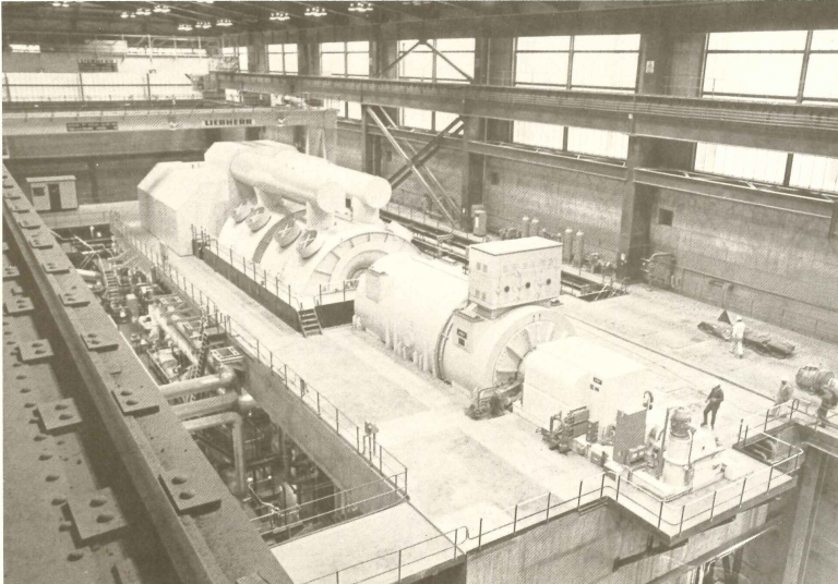
Turbines
There are six turbines at Tutuka manufactured by GEC Turbo-Generators of Rugby in the United Kingdom. Each turbine unit has high-pressure and intermediate-pressure cylinders have an internal and external casing to allow for fast start-up and rapid load variation. Foundations and supports for each turbine include 8 000 m³ or 20 000 tons of concrete.
Feed-heating plant
The condensate temperature in the condenser hot well is approximately 37ºC. Maximum system efficiency is obtained by re heating the condensate through numerous re heaters before returning it to the boiler. All the re heaters are of the surface type, in which water flows through tube nests. Steam extracted from different stages of the turbine heats the water by conduction through the tube metal.
More than 99.6% of the dust of fly ash is collected by the precipitators.
Each boiler has a capacity of 507 kg/s of steam. Feed water is supplied at a pressure of 22 MPa by two 13 MW electric pumps or one steam-driven pump.
Efficiency of the boilers at MCR is 93.9%.
The total mass of each boiler and its supporting structure is 9 800 tons and its cold water content is 185 tons. The furnace volume is approximately 13 000 m³ and the surface area of the heat exchange tubing totals 74 000 m².
A de-aerator situated between the low-and-high-pressure heaters removes entrained oxygen in the condensate and heats the water through direct contact with steam extracted from the turbines. The condensate is pumped from the condenser to the de-aerator through the low-pressure heaters by means of the main condensate extraction pumps. The condensate is then pumped from the de-aerator feed water tank through the high-pressure heaters to the boiler buy the boiler feed pumps. Final feed water temperature at 609 MW is 247ºC.
Condensers
The condensers are of the dual-pressure surface type. The vacuum inside the condensers is established by steam jet air ejectors and maintained in normal operation by water-jet air ejectors. Steam exhausted from the low pressure cylinder condenses over 22 552 brass tubes with a surface area of 23 400 m² each. Each boiler-turbine set has two condensers with a heat-exchange capacity of approximately 400 MW each.
Generators
Each generator is rated at MVA and generates 609 MW at full load. The send out capacity is 585 MW, the difference of 24 MW being used to run the auxiliary equipment such as feed pumps, mills, etc. Generator cooling is achieved through two systems. The stator and rotor are cooled by hydrogen at a pressure of 400 kPa, which is circulated through surface type water coolers by two fans locked to the rotor shaft. The stator windings and core are cooled by the circulation of demineralized water. The units generate at 22 kV and their output is transformed to 400 kV for distribution to the national grid.
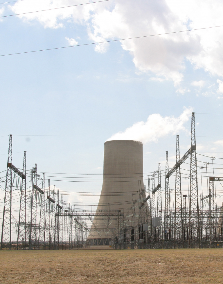
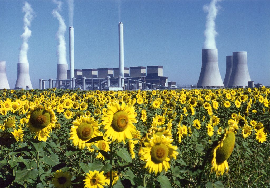
Chimneys
Tutuka’s two chimneys are each 275 m high. The speed at which they are constructed created new records. The sliding rate of 6.17 m a day is an achievement considered a world record for this record for this size of chimney. Each chimney contains three flues, providing one flue per boiler. The base diameter of the chimneys is 23 m and each stands on a reinforced concrete raft foundation. Approximately 40 000 tons of concrete were used in the construction of each stack. A service lift is installed inside the windshield for inspection and maintenance. The height of the chimneys allows the flue gases to be ejected through the normal inversion layer of the Mpumalanga Highveld atmosphere and dispersed over great distances.
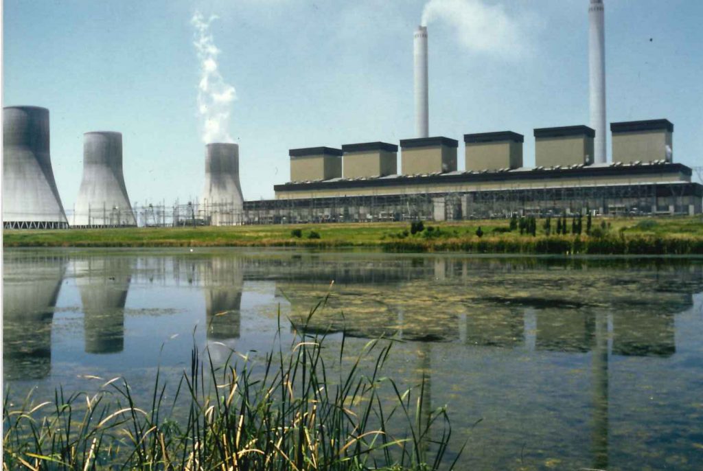
Cooling Towers
Tutuka’s six cooling towers have a total thermal load of approximately 19 000 Gj/h. The cooling towers are 143 m in height with a pond diameter of 108 m and minimum shell thickness of 180 mm. AT full load, the evaporation from one tower amounts to 30 Ml a day.
Water treatment
Raw water is fed from the Grootdraai dam through a pipeline to the local raw water reservoir. From there it flows by gravity to feed the cooling tower ponds and the raw water clarifiers. After cooling clarification and filtration the steam separates and is used for potable water and demineralized boiler feed water production.
During 1998 a decision was taken to combine the desalination requirements of New Denmark Colliery and Tutuka power station. Raw water concentrates up in the cooling towers and requires lime softening and clarification, which are done in the cooling water clarifiers.
Approximately 3 to 8.5 mega litres of saline water is produced at Tutuka power station a result of producing 3 600 MW of electricity. Most of this water originate from cooling tower blow down. The condensate is pumped from the condenser to the de-aerator though the low-pressure heaters by the main condensate extraction pumps. The de-aerator removes entrained oxygen in the condensate extraction pumps. The de-aerator removes entrained oxygen in the condensate and heats the water through direct contact with steam extracted from the turbines.
The condensate is then pumped from the de-aerator feed water tank to the boiler though the high-pressure heaters by the boiler feed pumps. The final feed water temperature at 600 MW is 247ºC.
Condensers
The condensers are of the dual-pressure surface type. The vacuum inside the condensers is established by steam-jet air ejectors and is maintained during normal operation by water-jet air ejectors. The steam exhausted from the low-pressure cylinder condenses over 22 552 brass tubes, which have a surface area totaling 23 400. Each boiler-turbine set has a condenser with a heat exchange capacity of approximately 750 MW.
Generators
Each generator is rated at 666 MVA and produces 600 MW at full load. The sent-out capacity is 575 MW, the difference of 25 MW being used to run the auxiliary equipment odd the turbine and boiler plant. Excess mine water is also fed to a cooling water clarifier, where it is mixed with cooling water blow down. Lime softening and clarification are then done to remove harmful chemical substances. The water is then fed to the Spiral Wound Reverse Osmosis Plant (SRO).
In a 3-stage SRO plant the water is pumped at high pressure through semi-permeable membrane that retains the salts and allows the clean water to go through. The permeate (produce) from the SRO stages 2 and 3 is returned to the cooling water circuit. The permeate from SRO stage 1 is used to feed the demin plant and the concentrated blow down (brine) is discharged to the ash system.
Cascading of water with different salinities is applied making the use of water very efficient. Only effluent that cannot be used for any other application is discharged, to the ash system via the boiler, coarse ash and fly ash systems, where it is used to condition the ash. All the rainwater from the terrace and dirty drain water are recovered to the cooling towers via the oil, grit and clarification plant and reused. Tutuka operates on a zero liquid effluent discharge water permit and hence no effluent water is released into the environment.
Ash collection and disposal
The new technique of dry ash removal used at Tutuka will save approximately 2 million litres of water per day when all six of the 600 MW sets are operative. The monthly savings equal the monthly water consumption of about 1 5000 household at an average of 40 kl per month. Two further advantages of this dry ashing technique are that rehabilitation of the ash dump can be done on a continuous basis and that the area, which previously had very little grazing potential can be returned to pasture.
At full load each boiler produces up to 150 tons of coarse ash and 1 500 tons tons of fly ash every day. The coarse ash is conveyed to the main twin ash conveyor belts via a separate grizzly and belt conveyor system.
The fly ash is collected from the precipitator hoppers by chain conveyors and lifted to concrete ash silos by vertical bucket elevators. The capacity of the silos is 2 600 m³ tons, effectively 10 hours’ fly ah is drawn from the silos and mixed with water or effluent in the ash conditioners to a consistency of approximately 15% moisture before it joins the main ash conveyors to be transported to the ash dump. The dumping stacking system can shape the dump height, width and inclination to suit the terrain and drainage requirements. The relatively dry ash is spread by mechanical stacker and compacted before being covered with topsoil so that the area can be rehabilitated. The main part of the system was designed and manufactured in South Africa with a local content of more than 90
New Denmark Colliery
The Colliery at New Denmark was started in 1980 and when in full production will be one of the largest underground mines worldwide dedicated to a single power station. It is designed to produce a total of 10.05 million tons of coal per annum at full output from two separate mines, and to do this on a continuous basis for 40 years.
One of the deepest coalmines in South African at 200 m, the colliery will mine a single seam averaging 2 in thickness. Coal recovery is totally mechanized with continuous miners and long-wall operations. Underground transport of men and materials will be a rail system. Belt conveyors are used to transport and coal, and the shaft conveyors have the biggest drives for this application in the country, each having 4 x 600 kW units. In each of the two mine shafts there are automatic winders, which can lift 60 tons or 300 men at a time. From silos at the surface, overland belt conveyors carry the coal 3.5 km from the Central Mine and 6.5 km from the North Mine to the rushing station close to the coal stockyard.
Power Giant Opened
The completed R4 billion Tutuka power tation near Standerton was officially opened by the Minister of Mineral and Energy Affairs Dr Dawie de Villiers. De Villiers De Villiers said Tutuka symbolises the challenges lying ahead in development appropriate energy strategies for a future South Africa. Indeed for that matter for southern Africa.
Tutuka is the third of Eskom’s news generating stations which were planned during the late seventies when growth in electricity sales was at an extreme high point. Growth in electricity sales has fallen during recent months and Eskom has excess generating capacity.
The modern stations have enabled Eskom to put older, less efficient stations into mothballs, or to start life extension programmes which will delay the need for new power stations into the next century. Tutuka’s first 600 MW generating set was taken into commercial service in May 1985. The sixth and final set of this 3 600 MW plant was brought into service in June. At one stage during construction more than 7 000 people were employed on site.
Welcoming the guests Dr John Maree, chairman of the Electricity Council said Eskom would not be able to undertake the building of multi-billion rand projects like Tutuka without international finance. The cost of financing power stations underlines the responsibility we have to make the best possible use of our national and corporate resources, both human and capital. “Because of the close link between electricity priced and economic activity we must supply the mining and manufacturing industries with affordable reliable power. As you will have seen our recent low price increase we are striving to make a contribution in fighting inflation” he added.
“Because of the close link between electricity prices and economic activity we must supply the mining and manufacturing industries with affordable, reliable power. As you will have seen with our recent low price increase we are striving to make a contribution in fighting inflation,” he added.
Tutuka has a number of unique technical features. It was the first station to use a dry ashing technique which will save millions of litres of water when the station is in full production. At the time that this ashing system was built it was the largest of its kind worldwide.
Members of international boards of Steinmuller and GEC Alsthom, two of the biggest contractors involved in the building of the power station. Dr Maree said he hoped Eskom would continue to contribute economically to the wellbeing of the area and fulfill its role as a responsible corporate citizen.
Generating capacity | 3 654 MW |
Operating | 5 shifts of 29 in 24 hours |
Fuel | – Mining company – Amcoal – Calorific value 24.5 Mj/kg (dry basis) – Ash content 22.4% (dry basis) – Total annual consumption 10 million tons – Coal silo capacity 27 000 tons – Boiler bunker capacity 4 000 tons/unit – Coal consumed at full load 1 500 tons/h |
Mills | – Manufacturer – Stein Industries – Type Tube mills – Number 6/unit – Speed 17 r/min – Rated output 62 tons/h |
Boilers | – Manufacturer – Steinmuller Africa (Pty) Ltd – Type – Benson – Number 6 – Maximum continuous rating 507 kg/sec – Final steam pressure 17.1 MPA – Final steam temperature 540ºC – Number of burners 24 – Height (roof to hopper) 94.0 m – Width at burner level 20.2 m – Depth at burner level 17.2 m – Boiler expansion (downwards) 340 mm – Approximate volume 13 080 m³ |
Turbines | – Manufacturer – GEC Turbine Generators (Pty) Ltd – Type Multi-cylinder, impulse reaction – Ration (generator output) 609 MW – Speed 3 000 r/min – Superheated steam pressure 16.1 MPa (abs) HP stop valve inlet – Superheated steam temperature 535ºC HP stop valve inlet – Steam pressure HP outlet 4 MPa (abs) – Steam temperature HP outlet 332ºC – Reheated steam pressure inlet 3.75 MPa (abs) – Reheated steam temperature IP inlet – Steam pressure IP outlet 0.42 MPa (abs) – Steam temperature IP outlet 252ºC – Inside condenser: – Average temperature inside condenser 37ºC – Heat consumption (MCR) 8 140 Kj/kWh – Steam flow 501 kg/s
|
Generators
| – Manufacturer GEC Turbine Generators (Pty) Ltd – Rated capacity 609 MW (MCR) – Terminal voltage 22 kV (50 Hz) – Power factor 0.9 (lagging) – Cooling medium Hydrogen at 400 kPa |
Generation transformers
| – Manufacturer ASEA Electric (SA) Ltd – Rated capacity 700 MVA – Terminal voltage: primary 22 kV – Terminal voltage: secondary 420 kV |
Cooling Towers
| – Number 6 – Type Hyperbolic natural draught – Overall dimensions: – Height 143 m – Pond diameter 108 m – Throat diameter 56 m – Diameter at top 49 m – Maximum shell thickness 180 mm – Nominal flow rate 13.8 m³/sec – Temperature – in 35ºC – Temperature – out 19ºC – Evaporation at duty point 1 270 m³/h – Nominal heat rejection 886 MW – Maximum guaranteed heat rejection 1 275 MW |
Circulation water pumps
| – Number 12 – Total capacity 82 m³/s |
Chimneys
| – Number (3 flues Each) – Height 275 m – Windshield diameter (Base) 23 m |
Water and effluent | – Total raw water consumption 167Ml/d – Cooling water 140 Ml/d – Potable water production 11 Ml/d – Demineralised water production 16 Ml/d – CW clarifier treatment 360 Ml/d – Spiral wound reverse osmosis plant capacity 12.5 Ml/d – Effluent vapour compression evaporator plant capacity 1.2 Ml/d – Mine effluent water recovery and treatment 6.0 Ml/d |
|
|