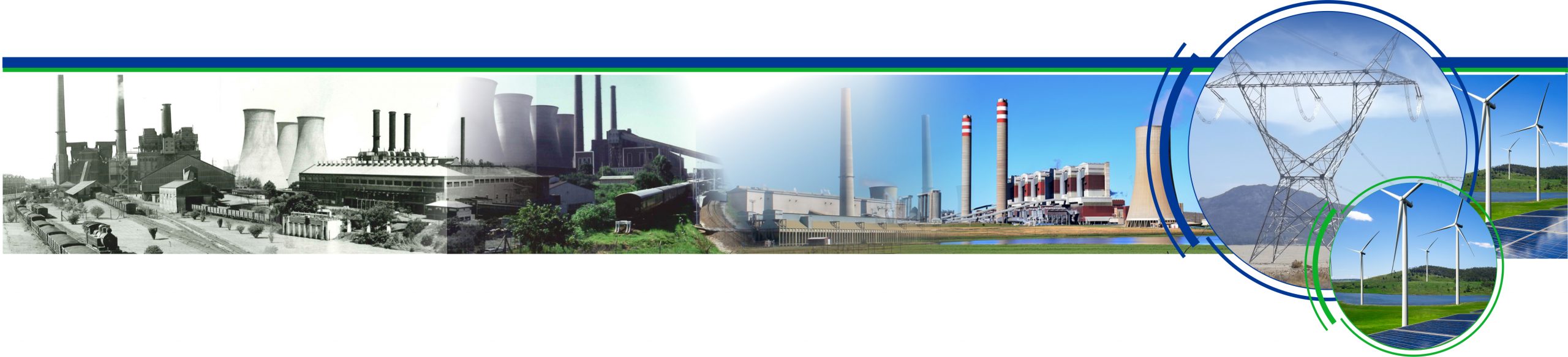

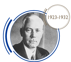
Established 1923
Eskom has been powering our nation since 1923 when the Electricity Supply Commission was established. Today still, it supplies more than 80% of electricity generated in South Africa.
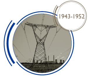
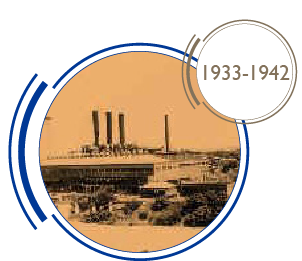
Eskom powers the grid with various types of power stations; from coal-fired to hydroelectric, nuclear, pumped storage, wind, and diesel. Our first Eskom designed station was Sabie River Gorge hydro station completed in 1927. The newest power station was the Medupi power station which was commissioned in 2021.
The past 100 years have included highlights such as around 90% of South African homes being electrified, as opposed to an average of 17% in the rest of Africa. Eskom also stood proud as Global Power Company of the Year in 2001. There have been many challenges since 2007 – the problems have been identified and a clear plan and vision have been
crafted going forward.
A vision for the future
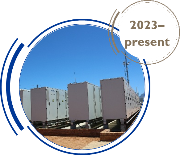
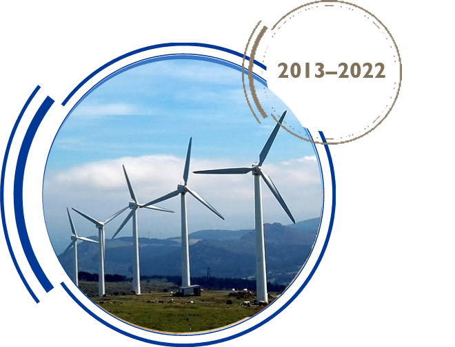
Eskom is moving away from being the sole supplier of electricity to being an enabler of electricity generation for South Africa. Eskom is also moving towards being a cleaner and more sustainable company through our Just Energy Transition (JET) programme. The aim is to achieve zero emissions by 2050 with an increase in sustainable jobs. This will be attained by repowering and repurposing the older coal-fired power stations, strengthening renewable energy generation on our own sites, and opening opportunities for independent power producers to build their plants on Eskom land.
The JET will focus on 3 elements:
• Just: doing better for people and the planet, growing localisation and industrialisation
• Energy: cleaner, sustainable electricity provision
• Transition: transformational change of business
By following a JET pathway, it will be possible to simultaneously spur economic growth, create sustainable jobs, and put emissions into structural decline – thereby ensuring an electricity supply that does not compromise economic growth.
Decommissioned coal-fired stations will be re-powered by building renewable energy plants on-site while establishing agrivoltaics projects to the benefit of local communities.
Here’s to 100 more…