Koeberg Nuclear Power Station

Emergency Plan Calendar 2024

Image of Koeberg nuclear power station
Play Video

Making electricity from nuclear power

Koeberg’s History
Construction of Koeberg began in 1976 and Unit 1 was synchronised to the grid on 4 April 1984, with Unit 2 following suit on 25 July 1985. It is situated at Duynefontein, 27km north of Cape Town on the Atlantic coast. Koeberg ensures a reliable supply of electricity to the Western Cape, one of the fastest growing regions in South Africa. It has operated safely and efficiently for over 28 years and has more years to go still.  

General
Koeberg, the only nuclear power station in Africa, has a pressurised water reactor (PWR) design. It boasts the largest turbine generators in the Southern Hemisphere and is the most southerly-situated nuclear power station in the world. Koeberg is surrounded by a 3 000 ha nature reserve owned by Eskom, containing more than 150 different species of birds and half a dozen small mammal species.

Low and intermediate level waste from Koeberg is transported by road in steel and concrete containers to a remote disposal site at Vaalputs, 600km away in the Kalahari Desert. The spent fuel, is stored on site in special pools quipped with high-density racking. 

Koeberg ranks amongst the safest of the world’s top ranking PWR’s of its vintage and is the most reliable Eskom power station. Koeberg has been awarded the NOSCAR status over 14 times by the National Occupational Safety Association (NOSA).

Contact details
Switchboard Tel:         +27 21 550 4911 
Visitors centre Tel:    +27 21 550 4667

Long Term Operation

Countdown to License Extension (21 July 2024)

  • 00Days
  • 00Hours
  • 00Minutes
  • 00Seconds

As part of the application to the National Nuclear Regulator (NNR) for the (LTO) Long term Operation (life extension) of Koeberg Nuclear Power Station, the NNR has directed Eskom to publish the Public information document (PID) giving the background and purpose of the application on the Eskom website for public access. 

Safety Case for Long-Term Operation of Koeberg Nuclear Power Station Rev 3
Openbare inligtingsdokument vir die langtermynbedryf van Koeberg-kernkragsentrale Rev 3
Public Information Document for the Long-Term Operation of Koeberg Nuclear Power Station Rev 3
Uxwebhu Lukawonke-wonke Lokwandisa Ixesha Lokusebenzisa Isitishi Sokuphehla Umbane Ngenyukliya SaseKoeberg Rev 3
K-27660-E Application to operate the Koeberg nuclear powe station (KNPS) beyond the timeframe established in the nuclear installation licence No. NIL-01 (Variation 19)
K-27660-E Attachment 1 - Updated LTO application
K-27660-E Attachment 2 - Memo of incorporation
K-27660-E Attachment 4 - Notice of registered SOC ltd.
K-27660-E Attachment 5 - Koeberg site map
LTO ENGLISH
LTO ISIXHOSA
ISO April

Operating method

Koeberg operates on 3 separate water systems. The water is also known as the coolant. In other types of nuclear reactors, gas is used as the coolant. The fact that the 3 systems are seperate is important because it means that the water in the reactor, which is radioactive but is in a closed system, does not come into contact with the other two systems and therefore does not contaminate the water in these systems.

The primary system takes heat away from the fuel in the (1) reactor to the tubes in the (2) steam generators The water is then returned to the reactor by means of a (3) pump. In this primary system, Koeberg uses a three-loop system which is kept under pressure by a (4) pressuriser hence the name Pressurised Water Reactor or PWR. As we have said, this system is closed and water from it does not come into contact with the secondary or tertiary system.

The secondary system is also closed. Water is pumped into the (2) steam generator. This water is allowed to boil and form steam which drives one (5) high pressure turbine, three (6) low pressure turbines and a (7) generator. The generator produces 921MW of electricity. Once the steam has driven the turbines it flows to the (8) condensers where it is cooled back to water and circulated back to the (2) steam generator.

The tertiary system is used in the condensers. The cooling water system for the condensers uses sea water at the rate of 80 tons/sec to cool the steam in the (8) condensers. Once it has cooled the steam down it is returned to the sea.

Reactor

The reactor vessel, which contains the nuclear fuel, is the central component of the reactor coolant system.

Its purpose is:

  • to contain the nuclear core, the internal structures and the control rod drive mechanisms:

  • to ensure a complete leak tightness and a sufficient resistance to internal pressure:

  • to contribute to radiation protection.

The reactor vessel is a weld-fabricated structure composed of the vessel body and the closure head. It is 13m high and 25cm thick. It is made of low-carbon steel with less than 0,2% cobalt. All internal surfaces of the vessel are clad with stainless steel to avoid corrosion.

Steam generators

The steam generator is a tubular heat exchanger of the natural circulation type, with mechanical drying of the produced steam. The primary reactor coolant flows through the tubes and gives up heat to the secondary feedwater on the shell side, producing steam at approximately 1 800t/h at rated pressure of 5,8MPa.

The steam generator is designed to withstand the thermal stresses associated with thermal cycling from cold to hot operating conditions. Particular care has been given to corrosion conditions (compatibility of Inconel tubing with primary and secondary coolant) and to possible flow-induced vibration problems.

The steam generator is a vertical shell containing the U-tube heat exchanger with integral moisture separating equipment.

The reactor water flows through the inverted U-tubes, entering and leaving through the nozzles located in the hemispherical cast bottom head. The head is divided into inlet and outlet chambers by a vertical Inconel partition plate. The interior surface of the bottom head and nozzles are clad with austenitic stainless steel.

Feedwater is pumped into a preheater section where it is heated almost to saturation temperature before entering the boiler section. Subsequently, the water-steam mixture flows upward through the tube bundle and into the steam drum section. A set of centrifugal moisture separators, located above the tube bundle, removes most of the entrained water from the steam. Steam driers are used to increase the steam quality to a minimum of 99,75% dry steam.

Manholes and handholes are provided in the bottom head and in the steam drums for maintenance and inspection.

Pump

The reactor coolant pumps circulate reactor coolant (water) through the reactor vessel and the steam generators tubes. There is one pump for each coolant loop, located on the cold leg of the steam generator. The reactor coolant pumps ensure an adequate core cooling flow rate and hence sufficient heat transfer.

The pump is a vertical suction, horizontal discharge single-stage centrifugal unit sealed with a combination of three water-cooled mechanical seals. The motor is a constant-speed, air-cooled, vertical. squirrel-cage induction motor

Pressuriser

The pressuriser and associated components establish and maintain the reactor coolant system pressure within prescribed limits and provide a surge chamber and a water reserve to accommodate reactor coolant density changes during operation. Relief valves connected to the pressuriser protect all reactor coolant system components from exceeding the design pressure.

The pressuriser has sufficient steam and water volumes to prevent uncovering of the heaters or discharging water through the safety valves during the most severe reactor coolant pressure changes expected. The surge line is sized to limit the pressure drop between the reactor coolant system and the safety valves with maximum allowable discharge flow from the safety valves.

The surge line connects the pressuriser to one reactor hot leg. The pressuriser is a vertical, cylindrical vessel with hemispherical top and bottoms heads, made of carbon steel with austenitic stainless steel cladding on all surfaces exposed to the reactor coolant.

When the pressure has to be increased the electrical heaters are automatically switched on and a certain amount of water is vaporised, increasing the steam volume with a consequent increase in pressure. There are 60 of these heaters distributed on three concentric circles around the surge line nozzle.

When the pressure has to be decreased, cold water is sprayed through a spray nozzle located in the top of the pressuriser which condenses a part of the steam and consequently decreases the pressure.

Turbines & generator

The steam generated by the steam generators drives a set of turbines. The steam drives one high pressure steam turbine and three low pressure turbinesat the rate of 1800 rpm. The turbines are connected to a generator. Each generator can produce a maximum of 920MW of electricity. The combined output of Koeberg’s two units (1840MW) is enough to supply the whole of the Western Cape with electricity in summer

Waste re-racking

Low level waste

This comprises of refuse which may or may not be contaminated with minute quantities of radioactive material. This waste is usually in the form of clothing, plastics, insulation material, paper and coveralls. This waste is generated in the controlled radiological areas of the power station. These items are sealed in clearly marked drums and stored on site until they are moved in one of the truck trips to Vaalputs. On average 475 steel drums and 158 concrete drums are shipped to Vaalputs every year. Vaalputs is the national repository for low and intermediate level waste some 500 km north of Koeberg.

Intermediate level waste

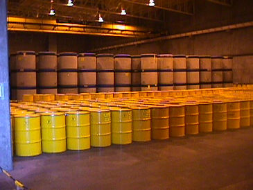
Intermediate level waste consists of purification sludges, spent resins, filter cartridges and irradiated scrap metal. This waste is more radioactive than the refuse but less radioactive than spent fuel. It is mixed in a very specific way with concrete and sealed into appropriately marked concrete drums. These drums also go to Vaalputs.

The concrete is constituted in such a way that even if a drum fell off a truck or broke open the radioactive materials inside could not harm the public because it has been sealed inside the concrete and cannot escape.

Spent fuel

High Level Waste (HLW) comprises the metal and mineral waste left over once spent fuel has been reprocessed to extract any re-usable uranium or plutonium. Alternatively, if a decision is taken not to reprocess, then spent fuel is itself considered HLW.

HLW has been around since mankind started its large-scale nuclear activities – 55 years ago. The volume of high level waste is small by industrial standards and it is housed safely. It constitutes no health risk to humanity.

So governments have no need to rush their decision about what they will do with HLW in the long term. They are in a position to weigh all the options on behalf of their citizens. As a result, very few governments in the world have committed themselves to a final disposal strategy

What is high level waste ?

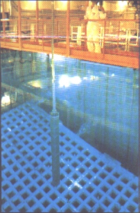
High level waste is fuel that has been used in the fission process. It is radioactively extremely dangerous. When it is removed from the reactor vessel it is stored in special “fuel pools”.

After ten years in a fuel pool it is “cool” enough to be moved into thick-walled casks which can be stored above ground for up to 40 years. Ten years has been chosen because in that period the bulk of the radioactivity from the short lived nuclides has decayed. This is known as dry storage and also interim storage.

A two-reactor pressure water reactor power station like Koeberg generates approximately 32 tons of spent fuel each year. Over a 40-year lifetime that would add up to 1 280 tons.

Each spent fuel assembly contains radioactive materials which fall into three categories.

The first category contains the fission products (such as caesium, iodine, stroulium, and xenon) which are created when uranium or plutonium nuclei are split. They are the most radioactive components of spent fuel when it leaves the reactor vessel for the fuel pool but they decay to low levels relatively quickly and after 1 000 years only about 400 GBq (10 curies) of the longest-lived fission products such as iodine 129, remain.

In the second category are the actinides, which are isotopes of uranium and heavier metals including plutonium. These are long-lived materials which take 10 000 years to decay to about 800 GBq (200 curies)

The last category contains the structural materials of the fuel assemblies which become radioactive through irradiation by neutrons. They only add a small amount of radiation to the whole spent fuel assembly total and decay in about 500 years to less than 200 GBq (5 curie)

How quickly does the radioactivity decay ?

A remarkable feature of spent fuel is that after one year of storage only 0.92% of the radioactivity remains in the assembly because the radioactive nuclides in the material decay so quickly.

After 10 years, which is the earliest time at which the assemblies would be taken out of the fuel pool, only 1% of the original radioactivity remains.

What is left after 10 000 years of storage is about 0,0002% of the radioactive content and most of that would be plutonium and others actinides. After this period the radioactivity has decayed to below what would have been there had the uranium been left undisturbed in the ground.

Radioactivity decays until it is harmless. In other words, spent fuel eventually gets rid of its own toxicity – unlike chemical toxic waste, which must be pro-actively treated to make it harmless.

Decommissioning

Power station operators have a choice regarding the decommissioning costs they incur. They can decommission the entire station soon after shut down and accept the cost of dealing with highly radioactive material. Or they can dismantle the non-radioactive parts of the site buildings immediately and leave the central block around the reactor itself for perhaps 50 years u and accept the cost of maintaining it for that period.

There are nuclear stations that have been shut down and decommissioned throughout the world . All decommissioning activities are supervised by independent nuclear safety authorities. In South Africa’s case this authority would be the National Nuclear Regulator . They establish safety requirements for the decommissioning workers and the public and ensure that they are adhered to. Great care is taken to prevent the spread of possible radioactive dust and liquid effluents

All organisation operating nuclear stations including Eskom are obliged to set aside funds to cover even tual decommissioning. These funds are set aside from the profit generated by the power station itself.

The options for Koeberg as far as decommissioning is concerned are:

  • It can be shut down, sealed and left under close security for as long as its reactor systems inside the containment buildings are radioactive

  • It can be shut down and the containment buildings filled with concrete to prevent any radioactivity present in the buildings from escaping

  • Under the Greenfield Option the Koeberg site can be rehabilitated to be left exactly as it was before the power station was built. This could only be done if the two radioactive cores and containment buildings were cut up and put into containers and buried, along with the waste and spent fuel.

  • After removal of the radioactive components the site could be used for another nuclear power station or a conventional power station.

  • It could be used as an industrial complex as it has all the infrastructure.

  • All the equipment within the containment buildings could be stripped of radioactive materials, and the buildings then used again.

Re-racking

Eskom has, since it began operating, looked at various options for storing it’s spent fuel.

The station is an exact copy of a French Pressurised Water Reactor (PWR). As such the station was originally designed to store spent fuel on site for only 5 years whereafter the fuel would be sent off for reprocessing. This process was and remains a very expensive option. During the late 1980’s the fuel pools were re-racked in order to store fuel for a 10 – 15 year period. This was state of the art technology at the time.

The fuel pools at Koeberg have now reached capacity and they will no longer be able to take any more spent fuel.

In 1996 after looking at options such as reprocessing, buying special storage casks and building a facility in which to house these casks or putting high density racks into the fuel pools a decision was taken to go for the high density racks. New technology now enables us to pack more spent fuel into racks making it possible to store all the spent fuel that will be generated over the lifetime of the station (approximately 40 years). These would number 11 000 for both units.

New racks

Two different storage regions will be created in the spent fuel pools. The first region will have 210 positions in three racks and will store the most reactive fuel. This is the fuel that has spent the least amount of time in the reactor and therefore contains relatively large amounts of U235 which could still undergo fission.

In this region the fuel assemblies are further apart so that there is no chance that they may start a spontaneous fission reaction. Criticality (the start of the fission process) is further controlled by using neutron absorbing materials in the construction so that the number of thermal neutrons in the region is always below that required to get a chain reaction. The racks are made up of stainless steel with plates of borated steel attached to the outside surface of each stainless steel storage channel.

Borated stainless steel is a stainless steel which contains as part of its chemical composition 1.7% boron. Boron is a very good neutron absorbing material.

The second region will contain the bulk of the spent fuel. The assemblies will be closer together since this will be fuel that has spent a longer period in the reactor and hence will have a lower residual amount of fissile uranium.

The racks in this region are constructed of the same materials as those in region one.

Interim measures

Due to delays in the re-racking project a decision was taken to use certain interim measures during the refueling outage in April 2000 and January 2001. Four spent fuel casks will each temporarily store 28 spent fuel assemblies. These casks were bought in 1996 and are specially designed to shield radioactivity. The casks were bought to provide Koeberg with flexibility in decision making should the occasion arise.

The casks

The casks weigh 97 740 kgs and are made of Ductile Cast Iron. The cast iron walls are 358mm thick. This thickness is optimal for three safety requirements

  • Providing strength needed for the cask wall

  • Providing shielding from the radiation emitted by the spent fuel and

  • Being manageable for transportation.

A layer of polyethylene rods has been built into the inside wall of the cask to provide a shield against the neutrons emitted by the fuel.

The cask is also designed so that the remaining thermal heat in the fuel assemblies is dissipated naturally. The advantage of this is that no heat removal systems which will require monitoring or maintenance are necessary. The heat losses occurs in the same way as it does when a cup of tea is allowed to cool down.

The casks are tested to cover three areas:

  • The structural ability of the cask to withstand strains caised by the use for which it is intended

  • The durability of the materials

  • The performance of the cask under unexpected or accident conditions

Prototypes of the Eskom casks have been dropped at various angles from a height of nine metres to see whether they broke or developed cracks through which fuel or radioactivity could escape. They remained sound.

They have been smashed into by a train locomotive traveling at a speed of 100kms/hr.

The re-racking project will continue and once all the racks have being installed the spent fuel in the casks will be moved back into the fuel pools and will remain there for the lifetime of the station.

Nuclear safety

Background

The Public Safety Information Forum (PSIF) is a meeting which takes place four times a year. It is used as a platform for residents residing within the municipal boundary of the Koeberg Nuclear Power Station to receive and ask for nuclear related information from the facility. Atendees of the meeting include community members, Koeberg Management, City of Cape Town – Disaster Management, Department of Energy and the National Nuclear Regulator (NNR)

Signed constitution

Public Safety Information Forum (PSIF) Minutes

Emergency Planning

Background

The Public Safety Information Forum (PSIF) is a meeting which takes place four times a year. It is used as a platform for residents residing within the municipal boundary of the Koeberg Nuclear Power Station to receive and ask for nuclear related information from the facility. Atendees of the meeting include community members, Koeberg Management, City of Cape Town – Disaster Management, Department of Energy and the National Nuclear Regulator (NNR)

Signed constitution

Public Safety Information Forum (PSIF) Minutes

Koeberg Coastal Waters Discharge Permit

Nuclear safety